Standardization closer for EDC-enabled 10-GbE
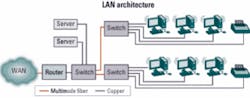
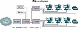
While today the dominant technology at the desktop is 100 Mbits/sec, there is a rapid adoption of next-generation technology supporting 1-Gbit/sec links over copper to the end user. Dell’Oro Group forecasts in excess of 100 million 1-GbE switch ports in 2007. This growth will result in a need to carry 10 Gbits/sec over the MMF installed between switches.
Historically, the adoption of new generations of Ethernet products has been as much about cost as about technology. The challenge for 10-GbE over MMF is to demonstrate the technical feasibility of new devices at a price point that will support their adoption. Electronic dispersion compensation (EDC) represents one technology that promises to help 10-GbE devices meet such technical and economic requirements for legacy MMF links of 300 m. EDC is at the heart of an emerging 10-GbE IEEE-standard PMD that should lead to small, low-power, low-cost components.
Standardization within the IEEE is an open process, which involves assembling a team of world class experts and providing them with a framework within which to work. The IEEE adopts a process based on “Robert’s Rules” for debating. The IEEE also has strict guidelines that prohibit discussions on commercial issues (e.g., product pricing, market share, and sales). Each contributor works as an individual, not the representative of a company, and holds one vote.
Individuals from many companies typically work with one another to develop support for their proposals, then submit them in the meeting as motions. Technical motions are adopted if they can achieve a 75% majority support during voting. Typically, the standards group will listen to multiple proposals, then accept one as the basis for writing a draft specification. Subsequent meetings then shift their focus to improving the draft and writing a complete specification.
In addition to the specification, the group also writes a compliance test document; the IEEE requires that a specification should support interoperability and be implemented by a defined set of tests. Final publication of the specification requires ratification by several different groups within the IEEE hierarchy. That can take time. However, the impact of the standards work is often evident in the market before completion as vendors move to quickly release products.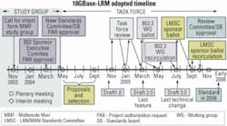
Dr. David Cunningham of Agilent Technologies is the chair of the 802.3aq group, which is tasked with writing the new standard PMD for 10-GbE over MMF: 10GBase-LRM. The timeline the group is working in will see the standard completed by next January (see Figure 2). At the time of this writing, the group is reviewing a draft specification written on the basis of an EDC proposal.1
Support of the installed base of legacy MMF represents an important requirement for 10-GbE devices; a need to install new fiber is clearly a barrier to mass-market adoption. However, legacy fiber presents a challenge to the 802.3aq Task Force. Much of the legacy MMF was manufactured and installed well before 10-Gbit/sec applications were considered; as a result, the fiber was never specified or characterized for such use.
To overcome this issue, the group is working to develop models for the fiber and gather data to demonstrate their statistical relevance. Simulations can then be made of the performance for the respective solutions using the models for the fiber. These simulations and subsequent interoperability testing need to demonstrate operation over the required link length (300 m) for an appropriate distribution of fibers.
The 802.3aq Task Force is developing two fiber models in support of its standardization effort. One is based on enhancements to the “Cambridge Model” used for GbE standardization.2 The other uses a Monte Carlo approach to derive fiber sets from a large body of measured data. The first of these models provides a relatively small set of worst case fiber types. The second helps to provide the statistical relevance for the Cambridge fiber set.
The Cambridge model involves building a set of refractive index profiles that have perturbations from the theoretical square law profile. Delay sets can be derived by solving the propagation characteristics of different modes as they travel down the fiber, with its given refractive index profile. The model used in GbE is often called the “81 fiber” model since it consists of permutations of four different perturbations, namely center-line defects, a variation <15-mm offset, a variation >15-mm offset, and core/cladding interface defects. Each perturbation has three different choices, hence the full set of 3 × 3 × 3 × 3 = 81 fibers.
The resulting delay profiles were then scaled to a maximum differential mode delay (DMD) of 2 nsec/km. That was done to align the model with statistical data from measurements.
Within the 802.3aq Task Force, this model has been further developed to capture the effects of kinks in the profile that have been shown to exist in the installed base. That was done by removing the abrupt change at the core/cladding interface (3 × 3 × 3 × 2 = 54), then adding a further 54 fibers with kinks giving a total of 108 fibers.3
In addition, the task force has also developed a model that uses measured data and has delay sets for over 5,000 fibers. That is being used to demonstrate the statistical relevance of the smaller, more tractable model. At the time of writing, this work is still in development, but a great deal of progress has been made, and the task force has accepted these models as the basis for supporting the standard.
All communication channels are ultimately range-limited and will suffer errors from one of two mechanisms: namely, noise or dispersion. Dispersion is the result of channel impairments and manifests itself as distortion of the received waveform. Multiple techniques have been developed to mitigate the effects of dispersion, for example, WDM, orthogonal frequency-division multiplexing (OFDM), pulse amplitude modulation-N (PAM-N), spread spectrum, and equalization.
With WDM, a high-speed data signal is divided into multiple lower-speed signals, which are then simultaneously transmitted by sending multiple wavelengths down the same fiber. This technique is conceptually simple and effective, but it does require multiple transmit and receive components as well as splitters and combiners, which in turn places limitations on the cost and size of components. That is the approach used with the 10GBase-LX4 standard. LX4 is an existing 10-GbE PMD standard that supports 10 km of singlemode fiber and 300 m of legacy MMF.
OFDM is another approach that uses multiple carriers. Here, the channels are deliberately spaced (in the frequency domain) such that each channel is orthogonal. OFDM is often used in wireless applications, since the technique offers benefits in terms of spectral efficiency. However, it is computationally intensive and not suitable for 10-Gbit/sec applications.
PAM-N and other multilevel modulation techniques could be employed for high-speed optical systems, although going to a more complex modulation scheme does bring with it limitations in terms of noise performance and increased requirements for linearity.
Spread spectrum is another approach that has been used in the wireless arena. With spread spectrum, each symbol is encoded into a data sequence. This sequence is designed with certain properties that enable it to share the medium, address the dispersion, and employ coding gain. Since this technique uses a “chipping rate” that is a multiple of the bit rate, it is not well suited to 10-Gbit/sec applications.
EDC is an attractive form of equalization because it allows real time processing on a 10-GHz bandwidth without a huge complexity burden. Essentially, the channel impairments are “corrected” with a digital filter whose tap weights only need adjusting at the rate required to adapt to the time-varying nature of the channel. For MMF applications, that is of the order of tens of hertz.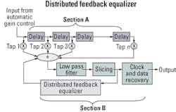
Figure 3 shows a schematic diagram for a distributed feedback equalizer (DFE), which is an architecture that could be used for this application. This type of equalizer employs the conventional linear feed-forward equalizer (shown as section A), with some additional feedback taps (section B). That makes the structure of the filter more powerful than a conventional linear equalizer, with the ability to correct for severe notches in the frequency spectrum of the channel.
Figure 4 provides insight into what the equalizer is doing. It shows a transmitter optical eye before transmission down the fiber. Here, the eye is shown without significant distortion. Figure 4 also shows a measured channel impulse response, h(t), for the fiber. Marked on this diagram is the bit period (100 psec) at the 10-Gbit/sec data rate. Clearly, the energy from the impulse has spread over multiple bit periods, and hence the signal at the receiver is significantly distorted. That is shown in Figure 4 as the signal entering the EDC block. The role of the EDC block is to create a filter whose response is in the inverse of h(t), the measured impulse response of the channel. Figure 4 shows that following the EDC block the signal distortion has been corrected and the eye is now open again.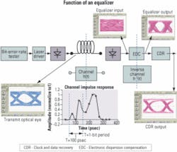
The EDC block uses an algorithm to determine the tap weightings employed by the equalizer and hence estimate the inverse of the channel h-1(t). In many applications, the packet structure includes a training sequence for the equalizer. That allows the equalizer to compute an error function based on the difference between a known data pattern and the soft waveform at the receiver. But for this application, there is no provision for such a training sequence in the protocol stack, and hence optimization is performed with “blind equalization.” Here the equalizer computes an error function by comparing an estimation of the received data with the soft waveform at the receiver.
A significant amount of investment is going into the development of EDC technology for 10 Gbits/sec over 300 m of MMF, with several vendors now offering early solutions. During 2005, it is expected that there will be numerous product announcements as companies release their final versions.
As mentioned earlier, the market need for 10-GbE over legacy MMF is evident today. Supporting this application with low-cost optical devices is likely to be a trigger point for creating a high-volume 10-GbE market. As a result, there is strong support for rapid commercialization of 10GBase-LRM technology. During 2004, there were multiple demonstrations of EDC offerings, and all the major building blocks required are available. In parallel with these developments, the standardization process is progressing well, with Draft 1.0 published last December.
This year, we will see the standard stabilize and move toward approval as well as multiple product announcements with volume shipments by yearend. Next year will see the standard achieve full ratification and the emergence of EDC for 10-Gbit/sec MMF as a high-growth market, enabling 10 Gbits/sec in the enterprise.
A low-cost approach to 10-GbE over 300 m of legacy MMF is required to enable the market and meet the needs of end-user networks as 1 Gbit/sec to the desktop becomes prevalent. EDC technology has the ability to mitigate the dispersion effects associated with 300 m of legacy MMF and enables transceivers of low cost, small size, and low power consumption. Several companies have developed this technology to the point where they are now supplying samples to customers. Meanwhile, the standardization effort within the IEEE is set for completion early next year. In 2006, we will witness the emergence of a volume market for 10-GbE over legacy MMF using EDC technology. This market is key to the continued development of Ethernet applications within the enterprise.
Michael Lawton is strategic marketing program manager of the Fiber Optic Product Division at Agilent Technologies UK.
- “NRZ EDC Proposal for 10GBASE-LRM,” presented by multiple authors to the IEEE 802.3aq Task Force in July 2004, http://grouper.ieee.org/groups/802/3/ aq/public/jul04/lawton_1_0704.pdf.
- M. Webster, L. Raddatz, I.H. White, and D.G. Cunningham, “A Statistical Analysis of Conditioned Launch for Gigabit Ethernet Links Using Multimode Fiber,” IEEE Journal of Lightwave Technology, Vol. 17, No. 9, September 1999.
- “Channel Modelling Ad-Hoc Report,” presented by multiple authors to the IEEE 802.3aq Task Force in November 2004. http://grouper.ieee.org/groups/802/3/ aq/public/sep04/penty_1_0904.pdf.