Side-polished fiber provides functionality and transparency
Removing enough cladding to create a window into the fiber core makes possible new designs for variable attenuators, modulators, amplifiers, tunable filters, and switches.
Optical networks require advanced optical components that can act on an optical signal without degrading it. The more transparent (fewer electronic components) these networks are, the more functions must be built into the optical layer, meaning that more passive optical components will have to act on the optical signal before it is regenerated. In such systems, the optical throughput of these components is an important design consideration.
One recently commercialized class of passive components is based on side-polished optical fibers with engineered overlays made from a variety of optical materials. The electronically controlled broadband variable attenuator shown in the photo, for example, has no moving parts. Other such devices include modulators, amplifiers, tunable filters, and switches.
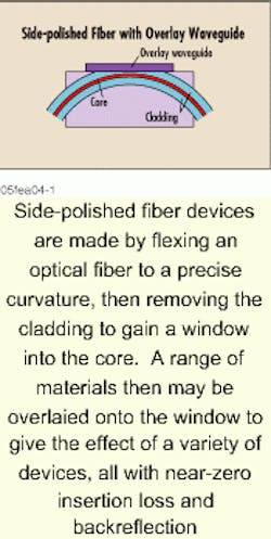
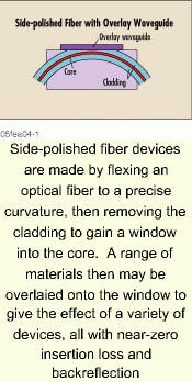
These components share a common architecture in which a singlemode fiber is flexed to a precise curvature and its cladding polished away so that the evanescent field can be accessed through a "window" onto the core (see Fig. 1). The optical signal can then couple from the fiber to an overlay material placed onto the window and back again. Use of different materials for this overlay gives rise to different optical functions in devices that feature near-zero insertion losses and backreflection. Referred to as side-polished fiber devices, they join other classes of passive components to fill out the toolkit of a fiber-optic system designer.
Relative meritsConceptually, perhaps the most straightforward way of building a fiber-optic device is to miniaturize an optical table, and this is how many components are made. Such free-space micro-optic devices include wavelength-division multiplexers (WDMs) based on interference filters, polarization-insensitive isolators, circulators, and mechanical switches. This technique is versatile and highly functional; in principle, anything that can be built on a table can also be built with fiber pigtails. However, components made in this way may suffer from losses associated with optical alignment and multiple surfaces, along with etalon-induced wavelength-dependent ripple. High-performance commercial components with acceptable insertion losses are the result of careful engineering.Integrated optical devices use single-mode waveguides fabricated with techniques similar to those used in semiconductor production. Components such as Mach-Zehnder modulators and array-waveguide grating multiplexers make good use of the ability of waveguides to control the optical path and manage the phase of the optical signal. Other devices using integrated optics include phase modulators and polymer thermo-optic switches.
In principle, integrated optics can be monolithically cascaded, minimizing device-to-device losses and enabling great economies of production. These devices still require alignment to the optical fiber, however, and this is a source of insertion loss. In addition, integrated optics frequently must be temperature-stabilized and often are inherently polarization-sensitive.
A third class of passive component is made directly out of optical fiber that can be fusion spliced. Examples include silica-based fiber amplifiers, dispersion-compensation modules, fused couplers, and several new devices based on fiber Bragg gratings. Making such components out of fiber eliminates the management of optical alignments, but only a limited range of materials can be fabricated into suitable fiber.
Side-polished fiber devices meld the low-loss performance of fiber devices with the material versatility of micro-optic-based approaches. These benefits were realized in couplers, polarizers, and evanescent field amplifiers.1
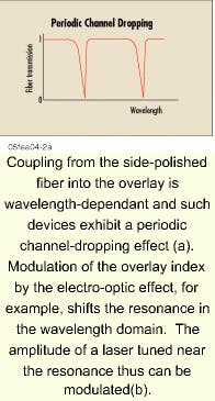
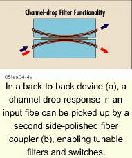
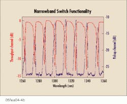
In the early 1990s, Walter Johnstone and his group at the University of Strathclyde (Glasgow, Scotland) investigated side-polished fiber devices in which the overlay was fabricated to slab waveguide dimensions. In this structure, only certain wavelengths that are phase-matched will couple from the fiber into the overlay, giving a periodic channel-dropping effect (see Fig. 2a).
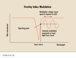
Any change in the refractive index of the overlay waveguide shifts this spectrum with respect to the wavelength. Consequently, if an input laser is tuned near the coupled wavelength, its amplitude can be modulated by a change in the overlay index (see Fig. 2b). The Strathclyde group subsequently used such a modulator to produce modelocked pulse trains at 3 GHz in an erbium fiber laser.2
Material options
The side-polished fiber architecture is amenable to a variety of materials, as different modulator projects have shown. The initial Strathclyde demonstration was performed with lithium niobate that had been fabricated into a slab waveguide and put into contact with the side-polished fiber. The group also has used spin-on polymers and other materials.
This versatility gives side-polished fiber modulators the potential to be particularly useful devices at high microwave frequencies. Their intrinsically short interaction region minimizes the potential for walk-off between the microwave and optical signals and can be used to significant advantage with the right electro-optic medium. Unlike other modulators, the side-polished fiber device does not require channel waveguide fabrication and so opens the door to candidate materials for which Mach-Zehnder devices would not be feasible.
Device options
Related in concept to an amplitude modulator is a fiber-optic variable attenuator, in which the amplitude modulation occurs over a much longer time. Unlike modulators, however, commercial attenuators must perform over a broad optical band to be useful in WDM systems-which, in turn, require a different overlay architecture.
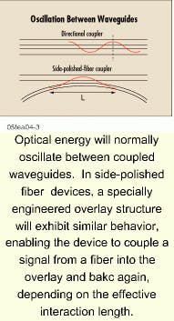
Optical amplifiers also can be constructed using the side-polished fiber architecture. Although evanescent field amplifiers were investigated early on, they exhibit rather low gains. A more-recent approach has been to construct the overlay such that the optical signal couples into it and then back into the fiber, in essence a single oscillation between a pair of coupled waveguides (see Fig. 3). This structure allows the entire mode to propagate in the gain medium, increasing the amplification that can be obtained compared to evanescent field devices. Of technological significance is the fact that many different kinds of gain materials can be used in this manner. We have built experimental amplifiers using Nd:YAG crystals, for example, that cannot be made into an optical fiber. Other crystalline materials can be used in side-polished fiber amplifiers, along with highly doped glasses that may prove too brittle for drawing into practical optical fiber.
A side-polished fiber device with an electro-optic overlay, as discussed, acts as a modulator for a single-wavelength source, but can be implemented as a tunable filter for multiple-wavelength inputs-a bandstop filter that ejects a particular channel from the input fiber.Another version of a tunable filter is a bandpass device, which allows a single wavelength, among many, to continue to propagate along the input fiber. Such a device is fabricated by polishing away the cladding into the fiber core to a "cutoff" condition in which the core can no longer contain the signal. In this format, a waveguide overlaid onto the window has the effect of returning specific phase-matched wavelengths back to the fiber. As before, an index-tunable overlay waveguide enables the wavelength tuning of the passband. The Strathclyde group successfully demonstrated tunable erbium fiber lasers using a filter of this design.6
The compatibility of side-polished fiber with practically any passive or active optical material gives designers a versatile tool to make high-performance fiber-optic devices for the increasingly transparent optical network.
References
- W. Johnstone et al., Electron. Lett. 27(11) 894 (1991).
- S. Creaney, W. Johnstone, and K. McCallion, IEEE Photon. Technol. Lett. 8(3), 355 (1996).
- A. Knoesen et al., In-line Fiber Electro-Optic Modulator Using Decal Deposition of Poled Nonlinear Polymers, Proc. Third International Conference on Organic Nonlinear Optics (December 1996).
- F. Pan, K. McCallion, and M. Chiappetta, Waveguide Fabrication and High Speed Intensity Modulation in Organic Crystal 4-N,N-Dimethylamino-4'-N'-Methylstilbazolium Tosylate (DAST(r)), Symposium on Organic Thin Films for Photonic Applications, American Chemical Society National Meeting (August 1998).
- K. McCallion, W. Johnstone, and G. Thursby, Electron. Lett. 28(4), 410 (1992).
- A. Gloag, N. Langford, K. McCallion, and W. Johnstone, Opt. Lett.19(11), 801 (1994).
Kevin J. McCallion is a fiber-optics engineer and Michael Shimazu is vice president of marketing and business development at Molecular Opto Electronics Corp. (Watervliet, NY) e-mail: shi [email protected].
