Crosstalk-induced jitter in high bandwidth LVPECL, CML and LVDS circuits
There are several ways to characterize jitter. In applications that require a multiplexer or crosspoint switch, crosstalk-induced jitter is an important specification.
By Bob Allen
Micrel Inc.
Jitter, which is defined as the deviation of a timing event from its ideal position, can be minimized in clock and data distribution systems by choosing high-performance LVPECL, CML, or LVDS differential series devices that guarantee jitter specifications for your particular application.
There are several ways to characterize jitter, including cycle-to-cycle, random, deterministic, total, and crosstalk-induced jitter. In the past, typically only cycle-to-cycle jitter was specified in ECL device datasheets. Currently, however, datasheets include all of the above mentioned jitter specifications.
The significance of each jitter specification is application-dependent. For instance, while cycle-to-cycle and total jitter are meaningful for clock applications, they aren't very useful in data applications. Cycle-to-cycle jitter represents the variation of periods between adjacent cycles and is an important timing concern for synchronous systems. It does not, however, give the designer an understanding of the effects of jitter over a long period of clock cycles. For that information, high-bandwidth component datasheets now also include total jitter specifications. Total jitter guarantees that no more than one output edge in 1012 output edges will deviate by more than the specified peak-to-peak jitter value.
For data applications, random and deterministic jitter are specified. Random jitter has a Gaussian distribution and is unbounded (rms). Common sources of random jitter include shot noise, flicker noise (1/f), and thermal noise. Micrel measures random jitter with a K28.7 comma detect character pattern.
Deterministic jitter is non-Gaussian and bounded (Pk-Pk). It is measured at specific data rates with both K28.5 and 223-1 PRBS patterns. Common sources of deterministic jitter include EMI and reflections.
The amount of jitter specifically induced by crosstalk is called crosstalk-induced jitter, which is the main focus of this article.
Basics of crosstalk-induced jitter
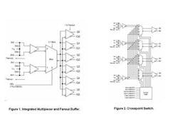
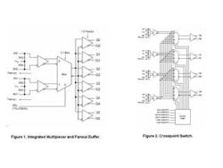
In applications that require a multiplexer or crosspoint switch, crosstalk-induced jitter is an important specification that indicates how much jitter can be expected at the output of these devices due to crosstalk. For example, many applications need to fan out one of two similar clock sources using either a standalone multiplexer or an integrated multiplexer plus fanout buffer (Figure 1). Other applications have similar data inputs, such as four OC-48 data streams, and need to route a specific input to a specific output using a crosspoint switch (see Figure 2). In these types of applications, crosstalk-induced jitter specifications allow the designer to understand how much jitter will be coupled from the unselected input(s) to the selected input.
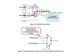
To illustrate, in Figure 3, the IN0 input is the desired output. However, due to crosstalk, the output consists of not only IN0, but of some IN1 as well. The selected signal is degraded and there is an increase in the amount of jitter present. Noise is capacitively coupled from the unselected input to the selected input at the front of the multiplexer inside the chip (Figure 4).
Historically, there hasn't existed a good definition for jitter-induced by crosstalk. Although it wasn't characterized in datasheets, older multiplexers and crosspoint switches had crosstalk-induced jitter numbers of ~ 4.6 psecrms. In high-performance systems in which other devices in the chain are contributing much less than 1 psecrms jitter, 4.6 psecrms is an excessive amount of jitter. And more troubling, since crosstalk-induced jitter historically wasn't defined in datasheets, a designer could remain unaware that his/her jitter budget had been exceeded due to a multiplexer or crosspoint switch until after boards were assembled and tested.
Working with crosstalk-induced jitter
Today, however, there are multiplexer and crosspoint switches on the market that not only define crosstalk-induced jitter, but well exceed the performance of other standard products. To achieve such performance, suppliers must recognize this issue and create a specification that quantifies the impact of crosstalk. For example, one company defines crosstalk-induced jitter as the increase in jitter measured at the output of a device while applying two similar differential clock frequencies that are asynchronous with respect to each other at the inputs. Leveraging such a definition, current-generation multiplexer and crosspoint switch devices are available that guarantee maximum crosstalk-induced jitter of less than 0.7 psecrms. Thus, a designer can go to layout with confidence that his or her board will not exceed the overall jitter budget.
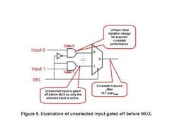
To achieve this large reduction in crosstalk-induced jitter, a new approach was needed to isolate one channel from the next. This has been accomplished by adding gates in front of the multiplexer inside the device. To illustrate, in Figure 5, the SEL is low so the Input 0 signal is selected. Input 0 passes through Gate 0 and into IN 0 of the multiplexer. Gate 1, however, is open and gates off Input 1 prior to the multiplexer. Thus, the Input 1 signal isn't present at the point within the chip that is most vulnerable to capacitively coupling the unwanted signal to the wanted signal path. This patented crosstalk multiplexer isolation implementation guarantees a designer <0.7 psec crosstalk-induced jitter.
With the inclusion of more jitter information than ever before in high-bandwidth datasheets, designers now have a much better understanding of a particular part's impact on his/her jitter budget in the intended application. By using today�s extremely low crosstalk-induced jitter multiplexers and crosspoint switches, a much lower overall jitter budget can be accomplished.
Bob Allenis a field application engineer at Micrel Inc.


