Testing small-form-factor fiber-optic links
These new style connectors may require modified test methods.
CHRIS VERNON, Tempo
Small-form-factor (SFF) connectors, which reduce connector size in order to increase the number of connectors that can fit on patch panels, outlets, and electronics, are gaining market share. The end result of all of this reduction in density is a reduction in the cost of the system. The TIA/EIA-568-B.3 optical-fiber cabling components portion of the commercial building cabling standard allows usage of SFF connectors as long as they feature TIA standardized interfaces and meet the performance requirements.
SFF devices are duplex connectors. That is a key difference between the SFF connectors such as the MT-RJ, Volition, and Opti-Jack and their ST or SC predecessors. Another important difference is that the two connectors that create a SFF connection are not always identical. In the case of the Volition and the Opti-Jack, the connection is made with a plug and jack configuration. In the case of the MT-RJ, the installed link portion of the channel has pins in the connectors and the patch cords do not.
These differences present some challenges when it comes to link testing. Proper testing procedures for SFF connectors can use test equipment with ST or SC interfaces as well as test equipment with SFF ports. Either test procedure can yield good test results, but the use of a tester with SFF ports will greatly simplify the test procedure.
The key types of passive fiber-optic tests are visual fault inspection, attenuation, optical return loss (ORL), and fault location using an optical time-domain reflectometer (OTDR). In local-area networking the key measurement is attenuation, determined by an optical loss test set. Some installers will test for faults using an OTDR, which is more the exception than the rule. If a system includes singlemode cable, the installer may also want to consider measuring ORL, which is rarely, if ever, found on multimode optical loss sets.Many advanced testers have sources for testing multimode systems at both 850 nm and 1300 nm. That is because the fiber itself has different loss characteristics at different wavelengths. At 850 nm, the loss from 100 m of fiber is approximately 0.5 dB compared to 0.1 dB at 1300 nm. A system that is within the link loss budget for 850 nm is also within loss budget at 1300 nm. It stands to reason that if you are going to test multimode cabling at only one wavelength, you should use an 850-nm source.
Visual fault identification is simply shining a bright visible light through the installation and verifying that the light is visible at the end of the cable. When purchasing a visual fault finder (VFF), it's important to compare the brightness of the sources on different units. Some devices use red light emitting diode (LED) sources and others use red laser sources. An added benefit to a laser VFF is that it allows users to identify the location of the faults in the cable. Microbends, or breaks in the fiber, cause light loss that can be detected through most cable jackets with a bright laser source. LED sources and simple flashlights, while less expensive, do not usually emit enough light to penetrate the cable jacket to help locate the fault.
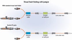
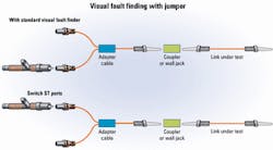
A VFF with an ST port requires the use of an SFF adapter cable to launch the light into the link under test as shown in Figure 1. This common testing situation will require the installer to hook up the VFF to one circuit of the duplex link using the adapter cable and visually inspect the light output at the end of the link under test. To test the second circuit, the adapter cable is switched to the other fiber. If the link under test runs from one end of the building to the other end, the installer must make two trips to verify both circuits.
Alternatively, using a VFF with an SFF port can eliminate the adapter cable and simplify the test. The link under test is connected directly to the VFF, which launches light into both fibers simultaneously using two independent lasers. By modulating the two lasers at different rates, the two circuits can be distinguished at the far end. That saves the installer time by allowing him to visually test both circuits simultaneously.A quick check of the quality of the termination is possible with a VFF with connectors using ceramic ferrules. The installer connects the VFF to the opposite end of the ferrule under inspection. By inspecting the light, the installer can often get a quick diagnosis of the termination problem.
When performing fiber tests, unclean ferrules are public enemy number one. Keeping a ready supply of cleaning accessories handy is a must. Special lint-free cleaning products remove dust and oil from skin without leaving lint behind. As an example of the effect of skin oil on a termination, attach a VFF to the end of a jumper cable that has ceramic ferrules. If you have a good termination, the light will pass cleanly through the ferrule. Now rub the ferrule opposite the VFF across the palm of your hand. You will likely see the ferrule glow due to the backreflection from the oil on your skin.
Attenuation, or cable loss, is extremely simple in concept. It refers to how much light is lost as it passes through the system. Where most of the confusion in link testing arises is in proper use of launch and receive reference cables. Therefore, it's important to understand the differences between Methods A and B of the TIA/EIA-526-14 Optical Power Loss Measurements of Installed Multimode Fiber Plant Standard and how to apply these testing methods to SFF connector systems. The TIA/EIA-568-B.3 standard ident ifies Method B as the proper method for multimode system testing. TIA/EIA-526-7 Measurement of Optical Power Loss of Installed Singlemode Fiber Cable Plant Method A.1 is used for single mode system testing.
TIA/EIA-526-14A Method A uses both a launch and receive cable when setting the reference point. This method of setting a reference point zeroes out one connection; when the actual measurement is taken, the tester will show the loss of the link under test and one connection. This method is commonly used in telecommunications where the links under test can be miles long and the losses of the connectors on the launch and receive cables are negligible. It has the advantage of ensuring that any imperfections in the receive cable are zeroed out when setting the reference.
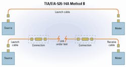
TIA/EIA-526-14A Method B is shown in Figure 2. This method uses only a launch cable when setting the reference point. Therefore, when the actual measurement is taken, the tester will show both the losses from the link under test as well as the connections at both ends. This test is preferable when the links are shorter and the connections make up the majority of the losses in a link, a common setup used in structured cabling systems for LANs.
An examination of the losses in an actual system will make the distinction between these methods clear. Consider the power budget for a generic cabling system that is connected to optoelectronics on each end by jumper cables:It's important to use Method B for LAN applications to avoid zeroing out one of the 0.75-dB connections to the basic link so the cabling system has no more than 3.5 dB of loss between the source and the receiver.
Most fiber testers available today and almost all of the testers currently in the field use ST, FC, or SC connectors on their fiber ports. An adapter cable is therefore required to test SFF links. Figure 3 shows an adapted test method for using existing ST-based equipment when testing an MT-RJ system. In the referencing step, the adapter cables and an adapter are used in order to make a connection that includes the launch cable. It's important to include the launch cable that will be used in the actual test, because the amount of light that gets coupled into the cable can depend on the actual connector/source interface. It is preferable not to disconnect the launch cable from the source after setting the reference point.
Because a connection is included in the reference point step, the tester needs to add a connection to make a two-connection measurement consistent with Method B. This modified Method B test procedure now has three connections in the actual measurement, but one has already been eliminated during the referencing step. That leaves two connections and the link under test.While this method allows the installer to correctly apply Method B, it requires three reference quality jumper cables: a launch cable, a receive cable, and the additional test jumper. It is recommended that these reference quality jumper cables be obtained from a test equipment supplier to ensure quality. That is particularly important for the additional test jumper because it is not involved in setting the reference point.
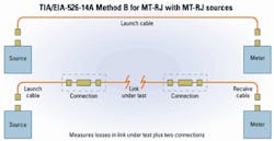
If customers have invested in one of the new fiber-optic test sets that offer an SFF adapter built into the source and meter, they can apply Method B without any modifications as shown in Figure 4. Once again, the launch cable is connected directly to both the source and the meter when setting the reference point. That prevents the elimination of a connection when taking the measurement and provides for the simplest measurement procedure. Since both the source and the meter also have a duplex SFF port built in, both fibers in the circuit can be tested with the push of a button.
SFF connectors offer multiple benefits. However, these devices may require different testing procedures in order to obtain the same result. Understanding the differences and applying proper technique improves the likelihood that the fiber link will operate properly when the electronics are hooked up.
Chris Vernon, RCDD, is a national ac count manager at Tempo, a Textron company. He can be reached via the company's Website, www.tempo.textron.com.
Lightwave is a monthly international publication focusing on fiber optics and optoelectronics, the technologies driving the growth, convergence, and improved performance of telephony, computer communications, and video. Lightwave provides technology news as well as applications and product information for corporate and technical managers and staff engineers. Lightwave's editors emphasize an alysis and interpretation in their reports on the technological impact of fiber-optic components, systems, and networks in these markets.


