Dual-loop laser drivers bring robustness to optical networks
A new breed of laser drivers raises the bar in optical transmission for long-term stability, manufacturability, and maintainability.
BRIAN RUSSELL, Analog Devices Inc.
Optical transmission is based on generating a constant optical signal, regardless of changes in a laser diode's environmental conditions or the progress of time. In short-reach applications, direct modulation of the laser is used to meet price and size requirements. These interfaces have traditionally used a combination of closed-loop and open-loop control systems. The open-loop approach is based on measuring environmental conditions and adjusting control parameters, assuming every laser would react in a similar way. This simplification often leads to performance compromise and maintenance problems in volume production.
This simplification has been sustainable in low volumes where the maintenance issues can be dealt with and impaired performance is acceptable as part of the price/performance tradeoff. However, as volumes increase, these compromises cost more in terms of human resources required to maintain a design and support second-sourcing issues.These early designs are now making way for new monolithic control systems that actively measure the characteristics of the laser and adjust the drive currents accordingly. Circuits performing these functions have been available for some time in larger-scale systems. Monolithic dual-loop control is bringing the associated benefits to system robustness in packages capable of fitting into small-form-factor electro-optic products.
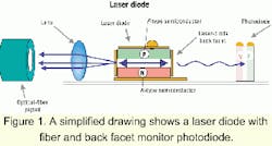
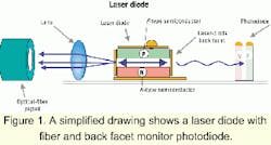
A laser diode used in optical communication is typically in a package that includes a fiber pigtail prealigned with the laser diode and a back facet monitor photodiode (MPD), as shown in Figure 1.
The amount of light coupled from the laser into the fiber is intended to stay constant over temperature even though the various mounting materials in the package expand at different rates. The MPD is reversed-biased and conducts current proportional to the number of incident photons. Thus, a measure of average optical power can be achieved by measuring the MPD current.
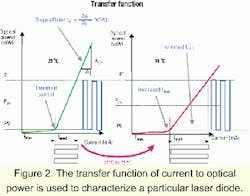
Laser diodes can be characterized by their transfer function of current to optical power (see Figure 2). Digital transmission occurs in the linear region to the right of the threshold current.
The challenge with maintaining a constant optical output is that the laser-diode transfer characteristics change over temperature and time. The threshold current increases and the slope efficiency falls off exponentially with temperature (see Figure 2). Additionally, over time, the laser threshold will increase and slope efficiency will decrease due to aging effects.Average power and extinction ratio are the two terms used to quantify a transmitter's optical output. Average power, as the name implies, is the average optical output power. Extinction ratio is the ratio between the optical power for a digital one and a digital zero.
System requirements demand that both average power and extinction ratio need to be kept constant. Usually, a bias current is adjusted to maintain a constant average power. The laser-diode driver switches a modulation current at the appropriate bit rate. The magnitude of the modulation current must be adjusted as the slope efficiency changes to maintain a fixed extinction ratio (see Figure 2).
Threshold current and slope efficiency vary from laser to laser, thus each transmitter must be calibrated in the factory once the laser diode and laser-diode driver are assembled on the printed circuit board.
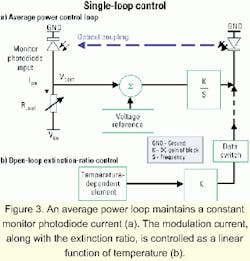
A simplified single-loop control diagram (Figure 3a) demonstrates average power control. This works only when the system guarantees an equal number of ones and zeros in the data stream by using block codes, scrambling, or Manchester encoding.During factory calibration of the optical transmitter, Rpset (a resistor chosen during calibration as a basis for reference) is adjusted until the desired average optical power is achieved. The control loop will then maintain an average optical power constant by keeping Vpset (Rpset times the average current of the MPD) constant, and hence the MPD current stays constant. Errors in average optical power will be present due to MPD tracking errors and control-loop effects such as the temperature coefficient of Rpset and input offset voltage of the control-loop input stage.
Figure 3b shows open-loop control of the extinction ratio. The modulation current and, hence, extinction ratio are controlled as a linear function of temperature. The rate at which the current changes over temperature is set to approximate the rate at which the slope efficiency falls off with temperature. That's typically a factor of 20% to 50% from 0°C to 70°C.
There are, however, several problems with open-loop control of extinction ratio. Possibly the most difficult problem with open-loop control schemes is their inability to compensate for laser aging, which leads to lower extinction ratios in the field as the system ages, reducing the robustness of the optical system over time.The rate at which a laser's slope efficiency falls off with temperature varies from laser to laser. That leads to different extinction ratios at high and low temperatures for different lasers.
Lasers must be statistically sampled in the lab to establish the mean rate at which the slope efficiency varies over temperature. The mean slope efficiency rate of change is designed into the transmitter control circuit. The mean rate of change between batches of lasers will have to be monitored in production.
Second-sourcing of lasers is made difficult. Not only do the high-speed characteristics of the laser have to match, but the temperature-drift characteristics also must match. Most factories want to be able to mix and match second-sourced parts without any changes to circuitry as supply chains vary.
These uncertainties must be taken into account by the electro-optic designer. A design must guarantee that the minimum extinction ratio is met-set down by the appropriate standards body. A maximum extinction ratio is defined by how close the designer is prepared to take the optical zero level to the laser threshold. That can lead to performance compromises in the optical eye as larger-than-nominal modulation currents mean the laser is operating closer to the threshold current, which can induce optical wavelength shift or slow the laser's transient response.
Interestingly, slope efficiency change over temperature is not a standard specification in a laser-diode data sheet.
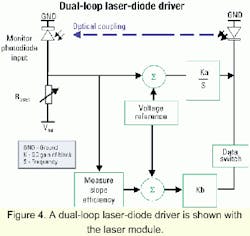
Dual-loop control (see Figure 4) defines a circuit that controls both bias current and modulation current based on measurements taken directly from the laser diode. Many dual-loop schemes are in operation today in firmware and circuit implementations. Several schemes are available in monolithic laser-diode drivers, providing very low board area and good control of the optical average power and extinction ratio.
There are various implementations used by dual-loop controllers with associated intellectual property and patents-some look at the data pattern and some impose a low-frequency signal on the eye. Looking at the data can be a major limitation, since the MPD is usually not fast enough to allow detection of P1 (optical power for digital one) and P0 (optical power for digital zero) in the data stream. Some laser drivers get around that by relying on several consecutive ones and several zeros in various header formats, which can make the device application and data rate specific as well as place speed requirements on the MPD.
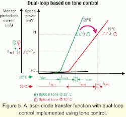
Some dual-loop implementations operate independent of data rate or MPD bandwidth by adding a low-frequency small signal into the optical waveform.Figure 5 shows a simplified example of a dual-loop scheme using tone control. This type of scheme has been used for some time, but may not be the type of scheme used in monolithic solutions. Figure 5 shows the laser-diode characteristic at 25°C and 70°C. In this example, a low-frequency tone is added to the modulation current that "sits" on top of the optical one level.
The control loop has a measure of the average power via the direct-current MPD current and the laser slope efficiency via the tone amplitude imposed on the monitor photodiode current. Therefore, the control circuitry can maintain a constant average power and extinction ratio by controlling the bias current and modulation current.
Whichever way the dual-loop scheme is implemented, it must measure two different parameters and use these parameters to control both average power and extinction ratio. Once that is achieved, many pitfalls of the single-loop implementation are eliminated.
With dual-loop laser drivers, the design of an optical transmitter can be greatly simplified for the following reasons:
- Laser-diode slope efficiency variation over temperature is tracked directly, not inferred in some open-loop manner.
- Laser-diode slope efficiency variation due to aging is directly tracked over time.
- Statistical sampling of laser-diode slope efficiency temperature coefficient is eliminated from the design process.
- Ongoing statistical sampling of laser-diode slope efficiency temperature coefficient is eliminated in manufacturing.
- Second-sourcing options are greatly enhanced as slope efficiency variation with temperature can now vary between lasers from different suppliers.
These features of dual-loop laser-diode drivers greatly improve the manufacture of optical interfaces in high-volume production, lead to tighter control of a transmitter's optical output, and result in a more robust optical system.
Currently, 2.5-Gbit/sec dual-loop laser-diode drivers exist in the market. They operate over a wide slope efficiency range to support low- and high-power applications. These devices are designed with a large range of currents and feature full monitoring and alarm functions to achieve the aforementioned benefits.
Brian Russell is a staff engineer for the high-speed networking group at Analog Devices Inc. (Limerick, Ireland).
