At the crossroads of 10-Gbit/sec transmission
A comparative look at 10-Gigabit Ethernet and SONET/SDH architectures as well as verification of hardware performance.
GREG LeCHEMINANT, Agilent Technologies
One approach to building bigger data pipes in the access network is to increase the capacity of Ethernet connections. Work is currently underway to develop a 10-Gigabit Ethernet (10-GbE) transmission standard, which is part of the IEEE 802.3 protocol, specifically IEEE standard 802.3ae scheduled for release this year. Considering the trend toward increased traffic levels, as well as the development of more bandwidth-intensive applications, 10-Gbit/sec capability in both LANs and MANs will become extremely important.
But to gain acceptance in a wide variety of applications, economical solutions must be developed; and to take advantage of the existing SONET/SDH infrastructure, there needs to be an effective way to migrate between two unique protocols. It is important to look at hardware solutions proposed for 10-GbE systems and contrast key performance specifications and verification techniques for 10-Gbit/sec transmission using SONET/SDH and 10-GbE.
10-GbE is the first Ethernet standard that will only function over optical fiber. Operation is over full-duplex mode and only with point-to-point connections, so collision detection protocols are not required. The physical layer (PHY) consists of the transceiver section and physical coding sublayer. Currently, there are several distinct transceiver architectures or physical media-dependent (PMD) sublayers being considered.
Exact optical bit rates depend on the application and whether it is a "LAN PHY" or "WAN PHY." The intent of the LAN PHY is to support existing Gigabit Ethernet applications with a 10 times expansion of bandwidth. The intent of the WAN PHY is to support "access" connections to SONET/SDH circuit-switched telephony equipment.In the wide WDM PHY PMD sublayers for LANs, four wavelengths-each at 3.125 Gbits/sec-are transmitted in parallel. An overhead of 2 bits for every 8 data bits (8B/10B coding) is used on each wavelength lane, yielding an overall payload of 10 Gbits/sec. For serial transceivers, there are 2 overhead bits for every 64 data bits (64B/66B coding). Thus for a 10-Gbit/sec payload, the optical bit rate is 10.3125 Gbits/sec. WAN PHYs exist for 850-, 1310-, and 1550-nm serial transceivers.
To be compatible with an OC-192/STM-64 system operating at a bit rate of 9.95328 Gbits/sec, and to include the proper framing structure, two levels of coding exist. First, 64B/66B coding is used for both WAN and LAN applications. Then a simplified SONET/SDH frame is added. Since SONET/SDH compatibility requires the overall bit rate to be 9.95328 Gbits/sec, the actual payload ends up being approximately 9.29 Gbits/sec.
The notation used to describe various transceivers is in a "10GBase-(X)(Y)(N)" format. The X term describes the wavelength of operation and Y term describes the physical control sublayer (PCS) and hence the coding of the overhead. The X term is one of the following: S, which is the short-wavelength 850-nm system (up to 65-m reach); L, the 1310-nm long-wavelength system (up to 10-km reach); or E, the 1550-nm extended-wavelength system (up to 40-km reach). The Y term is X, which uses 8B/10B coding; R, which uses 64B/66B coding; or W, which uses 64B/66B coding plus an STS-192 encapsulation for use with a SONET/SDH payload. The N term denotes the number of wavelengths and is implied to be a single wavelength, if no term is specifically indicated. For example, a 10GBase-EW is a single-wavelength 1550-nm-based system compatible with a SONET/SDH WAN; a 10GBase-SR would be a single 850-nm transceiver for use in a short-distance Ethernet link, and a 10GBase-LX4 would be a four-wavelength transceiver in the 1310-nm window.The lowest-cost, short-reach applications will use 850-nm vertical-cavity surface-emitting lasers (VCSELs). Medium-reach systems will use 1310-nm Fabry-Perot lasers, while the long-reach systems will employ 1550-nm distributed feedback lasers.
The characteristics describing transmitter performance in the IEEE 802.3ae standard have commonality with the characteristics prescribed for SONET/SDH transmitters. Transmit ters are characterized through measurement of the output spectrum, power, and waveform performance. Yet, there are also some differences.
For 10-GbE, a term not used for SONET/SDH, "optical modulation amplitude" (OMA), is used to describe the strength of the modulation on an optical carrier. OMA is simply the separation between the logic "1" level and logic "0" level. OMA is measured in units of power (dBm or milliwatts).
Historically, extinction ratio and average power have been used to describe the modulation strength of a laser. "Extinction ratio" is defined as the ratio of the logic 1 level to the 0 level, typically measured on an eye-diagram. Note that in contrast to OMA, extinction ratio is unitless. It indicates how efficiently a laser is converting available output power to modulation power but does not directly provide an absolute indication of the strength of the modulation. Extinction ratio specifications for SONET/SDH transmitters are typically in the 8.2-10-dB (6.6-10) range, depending on the application. The 10-GbE specification does include an extinction ratio parameter, but it is only 3 or 4 dB.
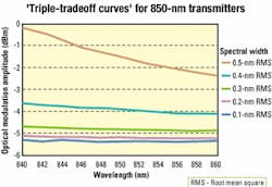
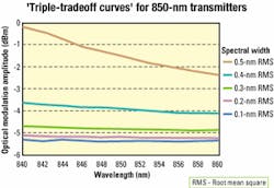
Why is there such a big difference in the two standards? One clue is the OMA specification. For a low bit-error ratio (BER), the system receiver would like to see the greatest difference possible between the 1 and 0 levels. That is measured directly with OMA. Conversely, the separation between the 1 and 0 level will be high for a high extinction ratio, as long as there is a reasonable average power level. As the extinction ratio becomes high, roughly 10 or more, both the 1 level and OMA will approach twice the average power. The 10-GbE standard has chosen to use OMA to achieve the necessary separation, while the SONET/SDH standard achieves separation with the combination of a higher minimum extinction ratio and an average power specification.In IEEE 802.3ae, OMA, spectral width, and average launch power are three interrelated parameters that are constrained by a set of "triple-tradeoff curves" (see Figure 1). For example, if the RMS spectral width is between 0.2 and 0.3 nm, and the center wavelength is between 844 and 846 nm, the OMA must be at least -4.72 dBm. However, if the spectral width is increased to a range of 0.3-0.4 nm, the OMA must be 1 dB higher or -3.72 dBm; if spectral width is between 0.2 and 0.3 nm, but center wavelength is 854-856 nm, OMA must be at least -4.83 dBm. The triple-tradeoff family of curves is generally complex and not a simple linear function and is used in recognition of the fact that required signal powers are affected by spectral width (dispersion penalties) and center wavelength (fiber attenuation).
SONET/SDH and 10-GbE specify the allowable shape of the transmitter waveform through an eye-mask test. A mask is used to define regions of the waveform where the waveform may not exist. For measurement consistency, the bandwidth of the measurement system is specified through the use of a reference receiver. For serial transceivers, 10-GbE has selected the identical reference receiver defined by SONET/SDH for 9.95328-Gbit/sec transmitters.
For 10-GbE, the oscilloscope used to measure the eye-mask is to be triggered by a "golden PLL." This phase-locked loop (PLL) has a loop bandwidth of 4 MHz and is used to derive a timing reference (trigger) from the transmitter signal. Thus, the derived trigger will "follow" the transmitter jitter as long as the jitter is at rates of 4 MHz or less. When this signal is used to trigger the oscilloscope for an eye-mask test, transmitter jitter that is less than 4 MHz is effectively common-moded out of the displayed waveform.
10-GbE does not intend to quantify jitter through an eye-mask test. Also, jitter that is slower than 4 MHz is not considered critical since the receiver in a 10-GbE system will have a similar recovered-clock timing system capable of tolerating jitter of <4 MHz.Specifications and associated test methodologies for jitter on 10-GbE are noticeably different than for SONET/SDH transceivers. In both instances, the intent is to verify that the relative time instability of transmitted signals is not excessive. 10-GbE takes the approach that there are essentially two types of mechanisms that cause transmitter jitter: deterministic and random.
Random jitter is unbounded. That is, there exists some probability that the waveform jitter will reach any level. Based on that, it is impossible to place a maximum tolerable value on the jitter. However, another approach would be to verify that the probability that the jitter exceeds some specific level is extremely low. This verification is achieved through a bit-error-ratio "bathtub curve."
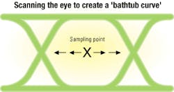
In the most basic sense, a BER bathtub curve is produced by feeding the transmitter signal to a BER tester. The sampling point (the amplitude decision threshold and the time at which bits are measured) is scanned in time across the "eye" while monitoring the BER (see Figure 2). If starting from the center of the eye, initially the BER would be zero, or too low to measure. As the eye crossing points are approached, jitter from the transmitter under test will occasionally result in edges being late on the left side of the eye and early on the right side of the eye. Bits measured at waveform edges can result in a "0" being interpreted as a "1" and vice versa. The BER at this point is then a measure of the probability of the jitter reaching this magnitude of time.
As the sampling point moves further into the eye crossing point, sampling on an edge becomes more and more likely; the BER will increase accordingly. This procedure will yield several sampling time/BER pairs. With BER on the Y axis and sampling time on the X axis, a bathtub curve is constructed. The slope of the bathtub curve is a measure of the random jitter, while the time axis offsets of the slopes are positioned by the deterministic jitter.
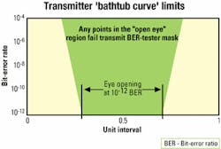
For 10-GbE, the transmitter jitter is defined to be the time separation between the bathtub curves at the BER=10-12 level (see Figure 3). Similar to the eye-mask test, the BER is clocked with a golden PLL with a 4-MHz loop bandwidth. Thus, the sampling point should actually track out or remove any jitter that is at a 4-MHz rate or slower. Essentially, only jitter in excess of 4 MHz is accounted for. While a BER tester provides an obvious measurement tool to perform this test, any technique that can generate the curve directly or indirectly can be valid.
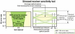
There is a straightforward approach to 10-GbE receiver testing (see Figure 4). The receiver must be able to achieve a BER of <10-12 when presented with the worst-case signal produced from lowest performing "in spec" parts. The test is called a "stressed receiver sensitivity test." The OMA is attenuated to a minimum level. The signal applied to the receiver is intentionally degraded with a combination of sinusoidal, random, and data-dependent jitter. The profile of the required jitter is essentially the complement of the transmitter jitter template. The jitter on the signal presented to the receiver must be as bad (or worse) than the worst-case allowable jitter from a transmitter.
SONET/SDH receivers must also be able to tolerate jitter. The power level of the optical signal is reduced to just "the onset of errors," then increased 1 dB. Jitter is then applied to the received signal and BER monitored. However, the jitter is strictly sinusoidal phase modulation. The jitter follows a specific template (jitter magnitude versus jitter rate) and is initially in excess of one unit interval (1 bit period) at low jitter rates. The rate of jitter is increased while monitoring BER. Higher jitter rates are performed with lower jitter amplitudes. This testing is referred to as "jitter tolerance."
A second important SONET/SDH jitter test is jitter transfer, which essentially is a measure of how fast the jitter can be and still be "tracked" by the receiver. Also, it is important that the receiver not exhibit any significant jitter gain in the re-timing process. If the filter design in the receiver clock recovery circuitry has peaking, the jitter on the recovered clock may exceed the level of the jitter on the incoming data. Systems with multiple repeaters, which derive their output timing from the input data, could exhibit excessive jitter gain, degrading the overall link performance. With 10-GbE, the timing of any transmission point is not derived from incoming data, so there is no need for a jitter transfer specification.
As 10-GbE is intended to be used in applications linking it with the SONET/SDH infrastructure, an obvious question is, how are the differences in specifications and methodologies for verification to be resolved? The standards bodies for the two architectures operate independently, so there is no "middleman" to sort out differences. Nevertheless, both groups are interested in forwarding the work, and the standards bodies are in communication with one another to develop working solutions. Perhaps 10-Gbit/sec transmission systems will exist where there is a true confluence of voice- and data-centric networks.
Greg LeCheminant is a measurement applications specialist at Agilent Technologies' Lightwave Div. (Santa Rosa, CA). He can be reached at [email protected].
