10-GbE transceivers: the future is now

The differences between Gigabit Ethernet and 10-Gigabit Ethernet transceivers, and all you need to know about how to select them.
DR. JOHN DALLESASSE, Molex Inc.
Having once been a mere event on the horizon, 10-Giga bit Ethernet (10-GbE) technology has become a well-defined, standards-driven tool for communicating in formation. Because 10-GbE is viewed as a point of convergence between traditionally separate data-communications and telecommunications market segments, the IEEE 802.3ae Task Force has completed a significant body of work that creates an efficient and versatile standard to enable optimized data transmission solutions for LAN, MAN, and WAN applications. Four major features of the standard enable this versatility, including:
- Definition of a set of physical media-dependent (PMD) sublayer types that span distances from very-short-reach (VSR) through 40 km.
- Definition of new electrical interfaces such as the 10-Gbit/sec attachment user interface (XAUI).
- Development of the WAN interface sublayer (WIS), a simplified SONET framer with provisioning for operations, administration, maintenance, and provisioning (OAM&P) to allow mapping of Ethernet frames into concatenated OC-192 data packets for Layer 1 transport over SONET OC-192 and SDH access equipment.
- Expansion of management data input/output (MDIO), which enables more extensive reporting on transceiver status.
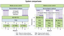
As signal speeds increase, so does the level of complexity associated with generating, transmitting, and receiving data while maintaining a sufficient level of signal integrity to maintain a low error rate. This complexity has driven optoelectron ic transceivers for 10-GbE to have more functionality and incorporate additional portions of the physical layer (PHY). A comparison of Gigabit Ethernet (GbE) and 10-GbE transceivers is worthwhile.
Many transceivers for GbE are nothing more than direct electrical-to-optical conversion de vices. The transceiver customer provides an 8B/10B-encoded signal to the transceiver at 1.25 Gbits/sec, and the signal is directly converted into an optical data stream. Information on the transceiver status (transmit fault and signal detect) or control functionality (transmit disable) is typically passed directly through dedicated low-speed logic lines.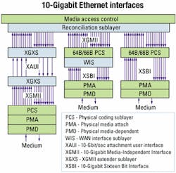
Pluggable GbE transceivers, such as GBICs and SFPs, provide some degree of additional functionality that allows better management and control and stringent regulation of timing and power (in-rush current). While these units typically have an I2C interface for accessing an EEPROM where transceiver information is stored, this interface is not typically used to report on the status or control the function of the transceiver. Generally, it is used to interrogate fixed registers that have information on the transceiver type, its capabilities, the manufacturer's part number, date of manufacture, and other vendor-specific data.
In contrast, transceivers for 10-GbE will be more complex, mainly due to signal speed. It is not practical to run 10-Gbit/sec data for long distances on low-cost board materials. For this reason, data from the media access controller (MAC) will be transmitted to the optoelectronic transceiver over a parallel electrical interface. The transceiver must incorporate the functions of clock and data recovery (CDR) for signal conditioning, encoding or re-encoding at the physical coding sublayer (PCS), and, normally, serialization and deserialization (SerDes, at the physical media attach-PMA layer). Therefore, optoelectronic transceivers for 10-GbE will not operate strictly at the PMD layer, as they did for GbE, but will also have PCS and PMA layer functionality.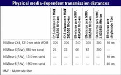
Another factor that will make 10-GbE transceivers more sophisticated than their GbE counterparts is the availability of a substantially enhanced MDIO interface that provides the option for improved transceiver status reporting and control. This interface is a key feature of 10-Gbit MSAs for hot-pluggable transceivers such as XENPAK.
While not all transceivers incorporate MDIO, its availability provides better diagnostic capabilities than those previously available for Ethernet systems. These diagnostics provide substantial value as "pure Ethernet" systems push from the LAN into the MAN and WAN and potentially into the home.
A change in serial PMD formats for 10-GbE from GbE is the use of a new coding scheme, 64B/66B, for optical transport. In GbE, 8B/10B code requires a 25% higher bit rate than data rate. To transport a gigabit of information, a data rate of 1.25 Gbaud is required. If 8B/10B coding were used for 10-GbE, a signaling speed of 12.5 Gbaud would be necessary. An IEEE 802.3ae 10-Gigabit Ethernet Task Force concern is that the higher bit rate would increase cost and not allow distance objectives to be met, leading to the acceptance of the 64B/66B code.
A final differentiating feature of the 10-GbE standard is the definition of the WIS. The WIS allows compatibility of the PHY with the data rate and format of SONET STS-192c and SDH VC-4-64c. It provides data to the PHY that has been adjusted at the MAC layer to the OC-192 data rate, framed with a simplified framer incorporating a minimal set of OAM&P functionality and scrambled per SONET requirements.
The primary advantage of the WIS is that it allows Ethernet data to be transported over SONET/SDH access equipment. Because it is concatenated, however, it must remain an OC-192 packet-and not channelized onto lower-speed SONET links. Thus, the WIS does not explicitly permit full interoperation of Ethernet and SONET systems. Transport over SONET equipment also requires optical transceivers with WIS functionality to incorporate clocks with a tolerance of 20 ppm as opposed to 100 ppm. This clock tolerance requirement enables seamless transport over SONET but increases cost.
In GbE, the optoelectronic transceiver is strictly at the PMD layer. For 10-GbE systems, PCS, PMA, PMD, and in some cases WIS functionality are built into the transceiver (see Figure 1).
The final differences between the 10-GbE and GbE standards are in the way that certain key transceiver performance parameters are specified. These changes include the use of optical modulation amplitude (OMA) instead of extinction ratio, the introduction of the "triple tradeoff curve" concept for OMA specification, and a change in the methodology for specifying jitter.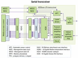
The use of OMA was proposed to facilitate high-speed direct modulation of laser-diode sources. For fixed modulation amplitude, semiconductor lasers have better high-speed performance as the average power is in creased. Unfortunately, moving up the light-current or L-I curve with a fixed modulation amplitude leads to a reduction in the extinction ratio. Maintaining a constant extinction ratio as average power goes up requires increasing modulation amplitude, putting more demands on the laser driver to meet a specification-driven as opposed to performance-driven parameter. Since the optical receivers are AC-coupled, the most important physical parameter is the difference in optical power between a received "1" and "0"-exactly the definition of OMA. The use of OMA thus allows specification of the parameter most closely correlated to performance.
The introduction of the triple tradeoff curve concept defines the specification for minimum OMA as a function of laser wavelength and maximum root mean square spectral width. The final significant change is the methodology for jitter specification and measurement. With the new method, transmitter jitter testing is performed using a bit-error-rate tester (BERT) scanned horizontally across the eye opening, measuring bit-error rate at test points. Measurements are performed at "TP3"-a point at the end of a fiber of specific modal bandwidth having a length equal to the maximum length specified in the IEEE 802.3 standard. The resulting "bathtub curve" must lie outside of a mask specified in the standard. Re ceiver jitter tolerance is measured using an input signal (with specific test patterns) that has been conditioned through the addition of jitter such that the input signal to the receiver falls within a bathtub curve mask.
Three optional data interfaces are specified for possible interconnection of the board to the optical transceiver: 10-Gigabit Media Independent Inter face (XGMII); 10-Gigabit Sixteen Bit Interface (XSBI); and XAUI. Most 10-GbE transceivers will have either an XSBI or XAUI interface (see Figure 2). XSBI and XAUI are currently used by two MSA groups for the electrical interface to the transceiver.
The XGMII interface consists of 32-bit-wide transmit and receive data paths, transmit and receive clock lines, and four control-signal lines on both transmit and receive sides. This interface will be internal for most implementations and is best suited for chip-to-chip or intrachip interconnects. On standard board materials, the maximum trace length for XGMII is limited to about 7 cm. When used in this fashion for chip-to-chip interconnects, high-speed transceiver logic conforming to EIA/JESD8-6 is the required electrical interface. The purpose of the XGMII is to have an interface that makes variation in the underlying PHYs transparent to the MAC.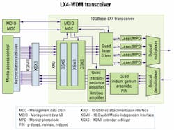
The XSBI interface consists of 16-bit-wide 8B/10B-encoded transmit and receive data paths, two transmit (four lines with clock [CLK] and CLK and one receive (two lines) clock signals, and one to four status and control lines (signal indicate, loss of synchronization, and two lines relating to loopback). The interface has low-voltage differential signaling electrical specifications defined by ANSI/TIA-644. Because of its origin as a SONET transponder interface (OIF SFI-4), XSBI has been specified as the transceiver electrical interface by two MSA groups. While a number of parts are currently produced with this interface, it is likely that XAUI will ultimately take the lead and become the interface of choice for optical transceivers.
The XAUI interface, which is gaining acceptance, has four transmit and four receive serial data lanes. The interface is self-clocked, and all XGMII data and control lines are mapped via the XGMII extender sublayer (XGXS) onto these paths. The nominal transmission speed on each of these paths is 3.125 Gbaud. Technically, XAUI is considered an XGMII extender, allowing data transmission over as many as 50 cm of standard board material. XAUI is AC-coupled and employs low swing differential signaling to minimize EMI radiation. Because XAUI requires the fewest number of physical lines, it is the interface of choice for MSA groups such as XENPAK and XGP that are targeting Z-axis pluggable transceiver modules.
The IEEE 802.3ae Working Group has standardized four PMD types to meet specific distance objectives for specific fiber types. These objectives are 40 km over singlemode fiber (SMF); 10 km over SMF; 300 m over installed multimode fiber (MMF); and 65 m over MMF (see Table). All PMD types for 10-GbE are designed only for full-duplex operation and require two optical fibers to form the data link.
The first distance objective, at least 40 km over SMF, is satisfied by the 10GBase-ER (LAN) and 10GBase-EW (WAN) PMD set. To reach longer distances without amplification, it is necessary to minimize attenuation in the link. For standard SMF, the loss per unit length has a minimum value near 1,550 nm. This PMD type uses serial data transmission at 1,550 nm to attain this distance objective and has several advantages and some key disadvantages.
The primary advantages are the ability to attain the 40-km objective and leverage technology developed for SONET OC-192 links. A final advantage is the potential to lock the wavelength onto a specific wavelength grid, enabling future WDM-based Ethernet systems to support capacities significantly beyond 10 Gbaud in the MAN and WAN.
The primary disadvantages are the need for a thermoelectric cooler and a single spectral mode wavelength-stabilized laser source with external modulation to minimize wavelength chirp. These requirements add complexity and cost. Given the cost-sensitive nature of Ethernet systems, the primary use of the 10GBase-E(R/W) PMD will be in the WAN and MAN, where a larger port cost can be tolerated.
The second distance objective, at least 10 km over SMF, was established to enable development of a lower-cost alternative to a temperature-stabilized, externally modulated link. The 10GBase-LR (LAN) and 10GBase-LW (WAN) PMD set satisfies this objective. This PMD uses a directly modulated, uncooled 1310-nm laser. The 1310-nm wavelength is selected because it is at the dispersion minimum of the fiber. As lasers are uncooled, this wavelength is required to avoid potential problems associated with laser wavelength chirp (see Figure 3).
On the transmit side, data from the MAC is passed through the XGMII interface to the XGXS, where it is mapped to XAUI. The XAUI signal travels to the optoelectronic transceiver, where the 8B/10B-encoded XAUI signal goes through CDR, is re-encoded into a 64B/66B signal, and is electrically multiplexed into a serial 10.3-Gbaud data path. The signal is the input to a laser driver, which is used to directly modulate a 1310-nm distributed feedback (DFB) laser, which converts the electrical bias and modulation currents into light for transport over the fiber. A separate control loop is used to monitor laser output to maintain constant power over temperature and time and report fault conditions.
The receive process is similar. A serial 10.3-Gbaud optical signal is received and converted from optical energy into an electrical signal via a high-speed photodetector, typically a low-cost indium gallium arsenide (InGaAs) PIN (p-doped, intrinsic, n-doped) diode. The electrical signal is amplified using a transimpedance amplifier (TIA), with the output of the TIA used to drive a limiting amplifier. The result is a 10.3-Gbaud, serial 64B/66B-encoded data stream. The signal travels through CDR, is electrically demultiplexed, and is re-encoded into an 8B/10B XAUI signal, which is passed out of the transceiver back to the MAC.
The third distance objective, up to 300 m over installed MMF, is satisfied by the 10GBase-LX4 PMD. This PMD type uses LX4-WDM in the 1310-nm wavelength region to reduce the maximum data rate on each wavelength channel. Since data rates are lower, the maximum possible transmission distances are longer, making LX4-WDM the only 10-GbE PMD type capable of supporting installed MMF plant at reasonable distances for LAN applications. It also supports 10 km over SMF, rendering it the most versatile PMD.
The LX4-WDM transceiver (see Figure 4) uses lasers on a wide (or coarse) wavelength spacing to lower the cost of lasers and passive optical components as much as possible. The centers of the wavelength bands are spaced 24.5 nm apart, at approximately 1275, 1300, 1325, and 1350 nm, and have a 13.4-nm passband. Other common names that have been used for LX4-WDM include wide WDM (WWDM) and coarse WDM (CWDM).
As with 10GBase-LR, data from the MAC is passed through XGMII and mapped onto XAUI by XGXS. The XAUI signal travels to the optoelectronic transceiver, where CDR and, optionally, realignment of the XAUI lanes occurs. The 3.125-Gbaud output from the XAUI retimer is fed into a quad laser driver incorporating an automatic power control loop to maintain constant average output power from the four DFB lasers over temperature and time. Light from the lasers is optically multiplexed onto a single optical fiber.
The receive process is also similar. Light from the receive fiber is passed through a passive optical component that optically demultiplexes four wavelengths on the fiber into single-wavelength signals. Each of the signals is converted from optical energy into an electrical signal with a dedicated InGaAs PIN photodiode. The electrical signals are amplified using a quad TIA and quad limiting amplifier and passed to the XAUI retimer where CDR and lane alignment once again take place. The resultant XAUI signal is passed out of the transceiver and back to the MAC through another XGXS/XGMII interface. Once again, MDIO and other status and control functions are contained within the transceiver.
The final objective of at least 65 m over MMF was established for VSR applications and is satisfied by a 10GBase-SR (LAN) and 10GBase-SW (WAN) PMD set. This set uses a directly modulated, 850-nm vertical-cavity surface-emitting laser (VCSEL) operating at 10.3125 Gbaud (LAN) or 9.95328 Gbaud (WAN). The primary justification for this PMD set is that it will be lower in cost than other PMD types.
While the distance is limited for installed fiber, the use of new, high-bandwidth (2,000 MHz-km) MMF permits the operation of links to distances of 300 m. The main disadvantage of this PMD set is the need for a restricted launch condition into the fiber to attain potential bandwidth, substantially increasing the complexity of VCSEL fiber coupling.
Proprietary (non-standard) implementations of 10-GbE-compatible PMD types may emerge. Examples could include WDM solutions in other wavelength regions (such as 850-nm and 1550-nm) and parallel-optics solutions.
It is difficult to predict what the next step will be for Ethernet. Sev eral speeds have been discussed, particularly data rates of 40 and 100 Gbits/sec.
Dr. John M. Dallesasse is a manager of group engineering for Molex Fiber Optics (Lisle, IL) and an active participant in the IEEE 802.3ae 10-Gigabit Ethernet Task Force.