Design challenges of a universal fiber-optic connector
The universal connector is compatible with all types of interfaces, regardless of the ferrule's size.
As the telecommunications market evolves, small-form-factor (SFF) connectors have redefined the market. One advantage of SFF connectors is that they can be fitted to SFF transceivers, which are half the width of those used a generation ago. With these accessories, fiber-optic designers can double port densities by fitting twice the number of connectors onto the same patch panel. The SFF connectors--such as the LC from Lucent Technologies, Volition VF-45 from 3M, MPO from Fujikura, MT-RJ developed by a consortium led by Hewlett-Packard and AMP, MU from Nippon Telegraph & Telephone, and MTP from US Conec, Ltd.--join an already impressive product group.
In the past, carriers bought test or transmission equipment with FC connectors that were compatible with all fiber connections. Today, connectors are developed to address specific situations; therefore, carriers now use several types of connectors in different sections of their networks. For example, the E-2000, popularized by Diamond, is used with high-power lasers. The special protective system of the E-2000 prevents high-power signals from causing it any harm. Similarly, SFF connectors such as the MPO, MU, LC, and MT-RJ, are used in switching hubs or with other transmission equipment, where port density is critical.
Because network operators build their infrastructures using a wide variety of connectors, testing can become cumbersome. The challenge for the manufacturer is to develop a universal connector that is compatible with all types of interfaces regardless of the size of the ferrule. Currently, manufacturers have to deal with two sizes of ferrules: 2.5 mm for the most widely used connectors like the SC, FC, and ST, and 1.25 mm for the emerging SFF connectors such as the LC, MT-RJ, MTP, and VF-45.
The importance of developing a universal connector will become even more obvious in the next few months when the ANSI/TIA/EIA-568B.3 standard is published. This standard does not recommend a type of SFF connector--unlike the TIA/EIA-568A specification, which endorsed the SC connector. It will therefore be up to operators to assess their network applications and choose the connectors that will best match their performance criteria.
Since network managers have the liberty of choosing from a wide range of connectors, each infrastructure may incorporate a unique assortment of connector interfaces. Maintenance technicians, called in to test several of these networks, must know beforehand whether their testing gear will be compatible with the connectors at the test site. With the advent of a fully universal connector, the maintenance crew, once on-site, could identify the type of connectors present, select that specific interface for their test equipment, and do the test. Moreover, instead of carrying several test jumpers to different sections of the network, a universal connector would allow the technicians to easily interchange from one interface to another.
Several factors have to be taken into consideration when designing a universal connector.
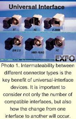
Intermateability between different connector types is the key issue when designing a universal device (see Photo 1). It is important to consider not only the number of compatible interfaces, but also how easy it is to change from one interface to another. One method is to have the connector interface perform a 90° twist on a base plate when changing from one interface to another. Keyholes on both the baseplate and connector interface ensure proper fiber alignment, especially in the case of angled polished connectors. Each keyhole has a different diameter to ensure the ferrules are always perfectly aligned, regardless of whether they are angled.A universal connector that offers interoperability between all standard 2.5-mm interfaces is already available. A similar offering for SFF connectors is in the works. The SFF model will allow users to easily interchange SFF connectors and standard 2.5-mm connectors.
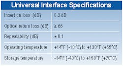
Even though ANSI/TIA/EIA-568B.3 will not recommend a specific type of SFF connector, it will stipulate a set of performance criteria that connectors should meet. One of these criteria is attenuation. The total attenuation (also known as insertion loss) given by a connector is the sum of many effects such as fiber-core mismatches, differences in numerical aperture between fibers, spacing between fibers, and other end losses. A well-designed universal connector will provide minimum attenuation because proper precautions will have been taken to minimize each one of the effects mentioned above.
A connector's return loss is also critical to performance. With connectors, return loss (or reflection) occurs when light passes between two materials with different indexes of refraction, also known as Fresnel reflections. These reflections can cause spurious modulations and instability on distributed-feedback lasers. Cable-TV systems are extremely vulnerable to these reflections because they use analog transmission. One way to minimize these reflections for cable-TV operators is to use angled polished connectors so the light reflected from the connectors will not be reflected back into the system.
The physical requirements of optical connectors include durability and the consistency of its loss measurements. The durability of a given connector is usually defined by the number of matings--connect and disconnect--it can withstand and still give optical performances within its specification. The repeatability of a given connector is its ability to repeat the same measurement after each mating. Today, the typical value for the repeatability of connectors on the market is ± 0.1 dB.
Connector performance can also be influenced by environmental factors. In addition to the temperature range and humidity level to which these devices must comply, they should be kept free of contaminants to avoid excess losses. Dust or dirt particles on connector endfaces can cause light absorption or scattering, rendering high connection losses and poor system performance. To avoid excess loss, a protective cap is integrated into the universal connector, which minimizes the amount of contaminants reaching the ferrule. The integrated cap is an important feature, because experience has shown that a removable protective cap is easily lost.To date, the universal connector has undergone extensive testing to determine its technical specifications (see Table).
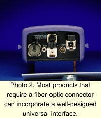
A well-designed universal connector can be offered on almost all products that require a fiber-optic connector (see Photo 2). The time saved, frustrations avoided, and hardships prevented are all excellent reasons to embrace the universal connector. u
Pierre Talbot is the OSP product manager at EXFO Electro-Optical Engineering Inc. (Quebec, Canada).


