Small-form-factor connectors present unique test challenge
Because of their attributes, SFF connectors require adjustments to standard test procedures to adequately measure performance.
The new generation of small-form-factor (SFF) fiber-optic connectors are extremely space efficient and will probably offer significant cost savings once they enter full-scale production. However, several of them offer a challenge to the person trying to test their absolute loss performance using current standard test procedures. In some cases, new procedures may give a better indication of the performance of individual connectors, but we have been able to develop hardware and procedures that allow testing with current EIA/TIA 526-14 methods.
Such a solution to the test problem is especially critical because these connectors are likely to be used with Gigabit Ethernet and other high-speed links, where higher bit rates creating lower link margins than are typical with slower networks and margins for error may be tighter. Test procedures must be accurate and reproducible.The LC connector is simply a miniature version of the SC or ST concept, with easy adaptation to test equipment and reference cables. (While they were not directly examined for this article, the LX.5 and MU connectors are structured similarly and should be equally easy to adapt.) The plug ends of the MT-RJ, Volition, and Fiber Jack can be adapted to connect directly to a meter, allowing one to make measurements of optical power and for calibration of launch cables for testing.
The sockets cannot be adapted to a meter and require patch cords to measure the power output of them. That adds an unknown loss to every power measurement and an additional uncertainty in every loss measured.For any test of a cable, it is absolutely mandatory to have reference cables that are known to be good, meaning the reference cables must be tested per FOTP-171 and be very low loss. Today, with the plug-type connectors we use that can be mated to each other, we test reference cables against each other (mated with a mating adapter) and discard those that have unacceptably high loss.
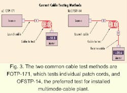
Note that both FOTP-171 and OFSTP-14 now include an additional option for setting the zero reference (see Fig. 2b). Originally, this option used a "bucket fiber" on the meter end on FOTP-171, Method A. The bucket fiber was a large core fiber used as a convenience for testing, adapting the connector on the cable being tested to the meter. It was not intended to be another matching cable to the cable under test as in FOTP-171, Method B or C.
Using a matching cable and setting the reference with the method shown in Figure 2b adds an additional uncertainty to the measurement unless one is careful to test the connection with a calibrated launch cable reference only. Since the loss of the connection between the two cables cannot be known, it's normal to assume the connection is good, which can be a very bad assumption when setting a reference value for further measurements. FOTP-171 had procedures to test the cables to ensure they were both good before making measurements.
Furthermore, referencing with two cables removes one connector loss from the measured loss, since it is included in the reference measurement. In effect, the loss of the tested cables relative to the loss of the reference cables is being measured, not the absolute loss!
For networks with relatively low losses, like Gigabit Ethernet and Fibre Channel, it is vitally important to have the loss specified with the method of testing defined unequivocally! Every network specification and EIA/TIA-568 Appendix H use the single cable reference to include both connectors when the cable plant is tested.
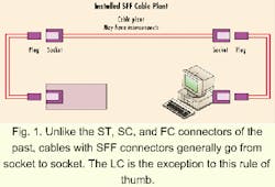
All of these procedures were developed on the assumption that connectors were male-type connectors and adaptable to plug directly into a meter. We can only use these procedures with the LC and Fiber Jack, however. The Fiber Jack, although a duplex plug/socket connector, can be mated plug-to-plug by using a special adapter, since the ferrules protrude beyond the end of the connector body. The other new SFF connectors are not so easily tested.
Ideally, we could take two patch cords that are already tested and known to be good, plug them into sockets on the installed cable plant, and measure the loss. Since most test equipment, especially sources, have ST connector interfaces, we will probably use patch cords that are ST-to-SFF (plug) connectors. The question is how to test those patch cords.Note we are testing a mated plug and jack, and the loss is for that pair. Traditionally, we are testing with the cable we want to test attached to the meter (see Fig. 3a), but here, we have the cables reversed. Since the directional variations on connectors are minimal, this is a good test of the connector performance.
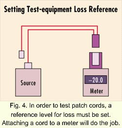
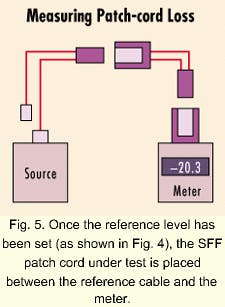
Now, if we want to test more patch cords, we have to go through the procedures illustrated in Figures 4 and 5 for every patch cord. This approach can be time consuming, but we can use the SFF socket cable as a launch cable with minimal measurement uncertainty.
To set up a launch reference with an SFF socket, use the procedures in Figures 4 and 5 to test two cables: the ST-SFF plug and ST-SFF socket cable combinations. Note the loss reading. Disconnect the cables from the meter and source (but not from each other) and reverse them.
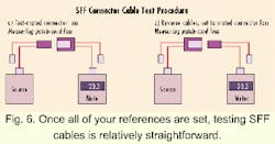
Now you have two options in setting a zero-loss reference. On the one hand, assuming the loss is the same in this direction, which is reasonable, set a new zero loss reference by adjusting the source power or meter to zero so the meter reads the same loss measured in the opposite direction. On the other, you can zero the meter with the two cables connected. NOW ALL YOUR LOSSES ARE RELATIVE TO THE LOSS OF THE REFERENCE MATED PAIR. This approach will cause lower loss connector pairs to have "gains" instead of losses, but as long as you know the measurement is relative, that should not be too confusing.So now you can test any patch cords with plugs as shown in Figure 6. You can replace the SFF plug to ST cable with another like cable and test its loss, or you can replace the meter adapter with an SFF adapter and test cables with SFF plugs on both ends.
The procedures above are written around testing only one fiber at a time, while all these connectors are duplex connectors. Three options exist for testing both fibers in each connection:
- Repeat the test with the second fiber (which is time consuming).
- Test with a meter and source at each end (which requires two sets of test instruments).
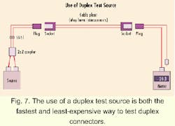
- Test with a duplex source (which tests in one direction only).
You can make a special launch cable by purchasing a ruggedized 2x2 coupler and terminating it in ST connectors on one end and an SFF plug on the other. This approach is sometimes impractical (the Volition patch cord uses special fibers, and some SFF connectors do not mate to two 3-mm jacketed cables), so a coupler with ST connectors can be used to adapt the source to the launch cable with an SFF plug.
Careful selection of the connections can usually balance the outputs of both fibers in the SFF plug. Reverse the connections at the fiber or reverse the ends of the coupler until the best balance is achieved. We have incorporated such a coupler in the Fotec FS370 source, recognizing the importance of testing duplex connections, and find it saves much time and effort in testing the SFF links.
Since the meter connection is a large-area detector, you can switch between the SFF plug and ST adapters.
Jim Hayes is president of Fotec (Medford, MA), and Eric Pearson is president of Pearson Technologies, Inc. (Acworth, GA).
