Transceivers as backup offer another port in a storm
New plug-and-play redundant transceivers can simplify the protection of critical connections in Ethernet networks.
Redundant transceivers, also known as fault-tolerant transceivers, add a higher level of integrity to Ethernet, Fast Ethernet, and Gigabit Ethernet networks by ensuring backup links between critical devices. A critical device such as a file server is often connected to the rest of the network through a hub or switch. A common problem with this configuration is that the server connection often relies on a single cable. If the cable link fails, the server is disconnected from the rest of the network.
That disconnect can prove costly if mission-critical data is lost or delayed. Having protracted downtime often erodes a company's bottomline as well as the integrity of the network. Past solutions to this problem such as mirroring some of the network architecture remain expensive and unwieldy. Redundant transceivers, on the other hand, offer an affordable way to build security and protection into the fiber network.
Today's lean organizational structures, interactive workflow, and tight deadlines mean a greater reliance on the network as a productivity tool. When the network goes down, productive work slows to a crawl--or stops altogether. As the quantity and speed of the data on the network increases, so does the relative cost of downtime.
Current demands for network speed and higher bandwidth have resulted in a migration to Gigabit Ethernet in many backbones--although the IEEE standards for fiber-based Gigabit networks were only adopted in April 1998. Currently, vendors are researching technology that will allow networks to operate at 10 Gbits/sec, a ten-fold increase over Gigabit Ethernet.
Network downtime can result from a wide range of unforeseen problems such as a seemingly minor software glitch or, at the other extreme, a fiber cut from a misguided shovel or backhoe. SecureTax.com, a Website used by hundreds of thousands of customers to prepare and file taxes, crashed earlier this year when a $200 network-circuit card failed. Another instance occurred a month earlier when an employee tripped on a power cord.
The cost of these "outages" can be catastrophic. In June, eBay's popular auction Website crashed and stayed down for 22 hours. The company estimates its lost transaction revenues during the blackout were somewhere in the range of $3 to $5 million. The blackout was blamed on a corruption of the files used for listing auction items and submitting bids--and it was entirely avoidable.
Increasingly, businesses with lots of capital dependent on a fully functioning network are turning to redundant transceivers as a backup to prevent these kinds of failures. These devices can be found everywhere from the trading floor to design studios.
Transceiver technology has been an integral part of Ethernet networks from the very beginning. The popular 10-Mbit/sec two-port transceivers continue to provide an easy and convenient way to link a network node from an attachment unit interface (AUI) port to either multimode or singlemode fiber, or to copper cable. Similarly, a media-independent interface (MII) Fast Ethernet port requires a transceiver with two ports to connect to the network.
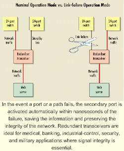
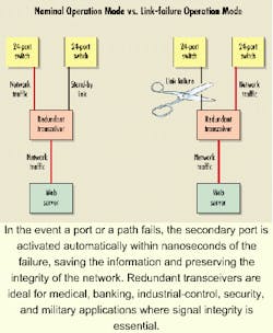
Redundant transceivers, whether stand-alone or chassis-based, have three ports, instead of two. While the main port links to a node the same way that the AUI or MII does, the two other ports--the primary and the secondary--are connected to the rest of the network. Thus, the primary port has two links to the network, only one of which is operational at any given time. In the event that the primary port or path fails, a secondary port is automatically activated within nanoseconds of the failure for Gigabit Ethernet or within milliseconds for Fast Ethernet, preserving the integrity of the network. Once the faulty link is re-established, the network rolls back to the primary connection, freeing the secondary port for use as a backup link.
For Gigabit Ethernet operation, redundant transceivers are configured with short-wavelength (SX) or long-wavelength (LX) ports. Network administrators can combine SX and LX ports on the same transceiver to convert a short fiber path (~300 m) into a longer run (7 km).
Redundancy is commonly used for backup solutions. Systems administrators often double the number of network interface cards in a computer's protocol control information slot in case of system failure. The principle is essentially the same: When one system fails, the other takes over. Another more-expensive backup method is to configure two identical network segments, which then serve as "mirror images" of each other.
Redundant transceivers offer the simplest solution to protecting network integrity--these devices can simply plug-and-play within the network architecture. Most transceivers operate at the physical layer of the Open Systems Interconnection (OSI) model. They do not require configuration or additional software. More importantly, the network can be up and running during their installation.
Most redundant transceivers will work with both multimode and singlemode fiber. These devices will support a migration to singlemode fiber, or a combination of singlemode (campus) and multimode (office and riser) connections. Fault-tolerant transceivers also work with unshielded twisted-pair (UTP) cable, and can be used to provide backup protection in fiber and copper networks.Redundant transceivers can be installed in two configurations. The first is as a stand-alone unit, which is about the size of a deck of cards. It has a small external power supply and in most cases a backup power supply. Stand-alone units can be placed virtually anywhere--from a wiring closet to a network floor. They do not have to be positioned close to a server. Network administrators can, however, take a cable off the server and connect it to the main port of the redundant transceiver. Typically, one of the primary and secondary ports runs a longer distance to some other node on the network to serve as a backup. Administrators can also easily attach the stand-alone units to the side of a cabinet or wall because of their light weight.
A different configuration is used when multiple ports require redundancy, such as a switch with 24 ports. In this case, the switch allows multiple connections to each port; therefore, each port creates its own network segment. Usually the switch is mounted in a wiring closet or a 19-inch rack. It is somewhat unmanageable to provide redundant links to several ports with stand-alone links. A cleaner solution utilizes a 19-inch rack-mount chassis, which can accommodate up to eight redundant modules; it mounts directly adjacent to the switch (see Figure). The modules can all be the same speed or some combination of 10-Mbit/sec Ethernet, 100-Mbit/sec Fast Ethernet, or 1-Gbit/sec Gigabit Ethernet. If several ports require fault-tolerant links, a chassis can be cascaded up to eight units deep in a single rack.
The incremental cost of redundant transceivers is just a few hundred dollars per node for either 10 Mbits/sec or 100 Mbits/sec. At Gigabit Ethernet levels, the cost could exceed a thousand dollars per node. This cost, however, is relative because it "buys" a manageable, inexpensive insurance policy against network outages.
Redundant transceivers also offer scalability. Network administrators can mix and match 10-Mbit/sec, 100-Mbit/sec, and 1-Gbit/sec redundant units as needed, including both copper and fiber. With this scalability, the network reaches higher speeds without a complete conversion or upgrade. Administrators can also selectively upgrade the network by migrating some users to higher speeds.
A typical redundant transceiver installation would involve a connection between a server and a group of users or involve an entire department. Traditionally, the connection would have had only one link between a hub and the server, exposing the department to network failure in the event of a power outage or other accident. With a redundant transceiver at the hub, two links to the server are established--only one of the links is active. The cables generally would not be buried in the same conduit or put in the same raceway in a building. They are routed differently--in case of a problem--ensuring that the network is protected against failure.
A more costly configuration involves two redundant, independent nodes. In this case, a redundant transceiver is again placed at the hub or switch. This time, however, one connection is to a switch or hub in one part of the building, the other connection to another part. Two mirror links with the same set of equipment is on either side. In the event of an emergency, one of the stations would remain up.
Finally, the plug-and-play feature of redundant transceivers allows these devices to be configured back-to-back. Such a back-to-back scheme provides one principal path from one node to the second node. But at the same time, this layout also results in three additional redundant paths for an even higher level of network security.
Configurations with redundant transceivers can vary, depending on the needs of the network. UTP and fiber can be configured together on the same network. All three ports on a transceiver can usually support either copper or fiber, and it's not necessary for all three ports to have the same media. A copper connection can easily be linked to a fiber network using a redundant transceiver allowing network administrators to upgrade the network piecemeal from a legacy system or just upgrade the parts of the network that require it.
Larry Castelli is a sales manager for LAN products in North America at Digi International (Minnetonka, MN).

