Progress in MU connector technology
New application demands mean technologies must continue to evolve, even after they have been introduced.
Shin'ichi Iwano and Shin SumidaNTTAs applications evolve, so must the component technologies that support them. For example, the MU fiber-optic connector is a mini-SC connector that inherits all the SC connector's assets. The MU connector exhibits a high level of performance while providing more than double the packaging density (see Photo 1). Another important advantage of the MU connector is its wide variety of applications, which range from cable connection to internal plug-in-type backplane connection (see Lightwave, October 1998, page 55).
The MU connector, therefore, provides a unified single-fiber connector interface for various systems, while all kinds of single-fiber connectors are used in the current systems. To enable a smooth transition from the current single-fiber connectors to the MU, further progress has been necessary in the MU's design. The result is better performance and a reduction in costs.
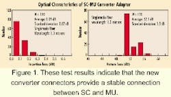
Conventional systems are mainly equipped with SC connectors. When converting from SC to MU, it is necessary to provide a way of connecting MU connectors to SC connectors. The diameter of the SC connector ferrule is 2.5 mm, twice the size of the 1.25 mm for the MU connector. When connecting an MU to an SC, these different-diameter ferrules should be precisely aligned to obtain a low insertion loss. In fact, the two ferrules must be aligned with an accuracy of 1 micron or better for singlemode applications.Figure 1 shows the optical characteristics of the SC-MU converter adapters. The average insertion loss is 0.09 dB with a standard deviation of 0.07 dB for a singlemode-fiber connection. The average return loss is 52.1 dB with a standard deviation of 1.9 dB. The insertion-loss change is less than 0.2 dB and the return loss remains greater than 40 dB in mechanical tests, including vibration and shock, and environmental tests, including temperature cycling as well as temperature cycling with high humidity tests. These results indicate that the converter connectors provide a stable connection between SC and MU connectors.
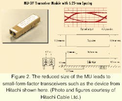
The original MU duplex plug has an outer shell in which two plugs are located 4.5 mm apart center to center. The original duplex plug, however, cannot be separated into two simplex plugs. Certain applications, such as premises wiring, require a duplex plug consisting of two simplex plugs combined with a binder clip. To achieve this setup, the new duplex MU plug features 6.25-mm plug spacing. An MU duplex binder clip makes it easy to combine two simplex MU plugs into one duplex MU plug and creates this 6.25-mm spacing.The 6.25-mm separation also enables the use of inexpensive TO CAN-type active devices to fabricate MU-type small-form-factor (SFF) transceiver modules. This technology has been used to develop new MU-SFF transceiver modules. Figure 2 shows an example of the MU-SFF transceiver modules provided by Hitachi Cable Ltd. These small transceiver modules (8.5 mm high and 13.25 mm wide) can be realized because of the small size of the MU connector. The MU-SFF transceiver is suitable for OC-48 use.
MU-SFF modules for original MU duplex plugs with 4.5-mm spacing are also available. The transceivers are produced by such companies as Infineon Technologies Corp. and Oki Electric Corp. This type of compact module is suitable for densely packaged systems.The MU also benefits from new fixed-attenuator technology. Fixed attenuators are required in such systems as cable termination frames (CTFs). At the CTF connection point, the input/output optical power is adjusted to a certain level by means of fixed attenuators to satisfy the required power condition. Photo 3a shows the newly developed MU fixed attenuator. The attenuator can be easily mated with or de tached from an MU adapter by a push-pull operation. These attenuators can be equipped to an adapter with a 6.25-mm separation. Figure 3b shows a new MU 8-port adapter with a 6.25-mm spacing equipped with MU fixed attenuators. Also shown is the MU fixed attenuators used with the clip-type MU duplex plug. Photo 3c shows the way MU attenuators are attached to an MU duplex plug, then connected to an MU-SFF transceiver with 6.25-mm spacing.
Special systems such as DWDM equipment require flat attenuation in the 1.5-micron wavelength region. The MU fixed attenuators offer such a flat attenuation. The deviation in attenuation in the 1.53- to 1.62-micron wavelength range is less than 0.5 dB for an attenuation of less than 10 dB and less that 1 dB for an attenuation greater than 10 dB.
NTT produced 1.25-mm-diameter zirconia ceramic ferrules for MU connectors in 1993. Zirconia ceramic ferrules provide excellent levels of performance. This ferrule, however, requires a complex manufacturing process, which results in a relatively high cost. Some application areas require inexpensive MU connectors with moderate performance levels. High-precision plastic-molded MU ferrules are now available for such applications.
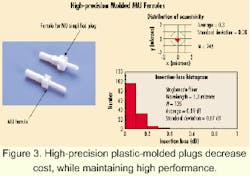
Figure 3a shows the newly developed plastic-molded MU ferrules. The cylindrical alignment portion and the ferrule flange are fabricated simultaneously. The ferrule shape can be easily changed by changing the mold. Ferrules for MU simplified plugs use the same technology.The ferrule material is a liquid crystalline polymer that we selected because of its good fluidity and capacity for replication. Figure 3b shows the eccentricity distribution of the minute holes in relation to the outer diameter of the developed MU plastic ferrules. The average and standard deviation of the eccentricity are 0.3 and 0.08 micron, respectively. These values are sufficient for singlemode-fiber connection applications.
Figure 3c shows the insertion loss measured with singlemode fibers. The average value and standard deviation of the insertion losses are 0.09 dB and 0.07 dB, respectively. NTT has performed various mechanical and environmental tests on the plastic ferrules. These tests were also undertaken with the condition that the plastic ferrules were butted to conventional MU zirconia ferrules. All these test results indicate good performance levels, which reveal that the plastic ferrules can be used not only for multimode-fiber applications, but also for singlemode applications.
It is important to reduce the cost of fiber-optic connectors when accelerating the construction of fiber-optic network systems. The MU connector is no exception.
The newly developed low-cost MU plug is shown in Photo 4a. NTT redesigned the structure of the conventional MU plug to increase its cost competitiveness by developing pre-assembled parts that take account of applications involving automatic or field assembly.Meanwhile a new polishing ma chine (Photo 4b) reduces the ferrule polishing cost. With the MU connector, the ferrule area to be polished is roughly one-tenth that of conventional connectors. The design of the machine takes advantage of this smaller polishing area, thus establishing the optimum polishing conditions. The polishing process has been reduced from three to two steps and no longer requires expensive abrasives such as diamond slurry. As a result, the polishing cost can be reduced to less than one-third that of conventional methods.
A plastic MU adapter (Photo 4c) and the MU simplified receptacles (Photo 4d) provide further economies. These technologies have greatly reduced the manufacturing cost to the point that it is now possible to manufacture MU connectors less expensively than SC connectors.
The MU connector application area is rapidly spreading to accompany such advances in network technologies as fiber-to-the-home (FTTH), DWDM, and IP over photonic networks. Last October, the National Committee for Information Technology Standards (NCITS) Technical Committee T11.2 adopted the MU connector for Fibre Channel applications and specified it in the appropriate T11.2 document. The demand for MU connectors is increasing along with this rapid expansion of the MU application area, and the number of MU connector manufacturers is increasing.
That means it is becoming increasingly important to maintain compatibility and exchangeability between MU connectors from different producers. As a result, NTT has established a certification service, provided by NTT Advanced Technology Corp. and designed to be open to all manufacturers at a reasonable cost.
Given the explosive increase in demand for fiber-optic network traffic, NTT plans to carry out a full-scale introduction of MU connector technology into its communication networks, while promoting a shift from SC to MU connectors, as a way to accelerate the economical and efficient construction of next-generation fiber-optic networks.
Shin'ichi Iwano, Dr. Eng., is senior manager, and Shin Sumida, Dr. Eng., is group leader, senior manager, Photonic Integration Project, at NTT Photonics Laboratories (Tokai, Naka-gun, Ibaraki-ken, Japan).


