Raising dispersion tolerance to increase distance
When service providers upgrade their metro networks to 10-Gbit/sec transmission speeds, they must overcome the chromatic dispersion (CD) limitations of SONET/SDH single-channel and DWDM systems. Once these limits are reached, optical signals must be regenerated, increasing network equipment expenditures for service providers at a time when cost reductions are a necessity.
Several techniques are being developed to extend dispersion limits and eliminate as much expensive regeneration equipment as possible. One approach uses transmit side signal processing to achieve spectral shaping of the optical transmission to make it more tolerant of dispersion.
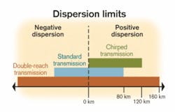
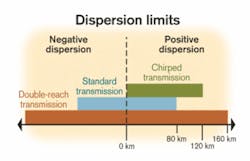
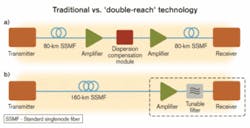
As the signal propagates through fiber, dispersion typically distorts the signal. When the signal reaches beyond a certain distance—typically 80 km for 10-Gbit/sec transmission speeds—the signal becomes so distorted that the receiver has trouble differentiating between the 0s and 1s. At that point, errors result as the equipment tries to determine what was sent.For carriers to go beyond 80 km at 10-Gbit/sec transmission speeds, the network requires regeneration equipment that involves optical-electrical-optical (OEO) conversion. An alternative method is to use optical dispersion compensation modules (DCMs) to undo the effects of fiber dispersion. This equipment consists of dispersion-compensating fiber (DCF), which is lossy, followed by an optical amplifier (OA) to offset the loss (see Figure 2a). Although not as expensive as regeneration, DCMs add substantial cost to the network.
To extend the distance beyond 80 km also requires the use of inline OAs to overcome fiber attenuation. This optical loss is about 0.25 dB/km in the 1.5-µm wavelength region, representing a 20-dB loss over 80 km of SSMF.
Any signal will at some point begin to degrade and eventually fall apart as it travels a long distance down the fiber. The idea is to create a signal that will travel a much longer distance before that happens. One approach involves signal processing on the transmit side before launching the optical signal onto the fiber or after the optical detection on the receive side. Transmit signal processing can condition the launched optical signal to tolerate a larger amount of dispersion, while receive side processing attempts to undo the distorting effects of transmission.
A greater dispersion tolerance is achieved by narrowing the optical spectrum of the transmission. Since the detrimental effects of dispersion are proportional to the square of the signal bandwidth, significant narrowing of the spectrum can increase the signal's robustness to dispersion, extending the dispersion-limited distance.
This narrowing of the spectrum is achieved by employing signal processing and advanced modulation techniques on the transmit side. The outgoing data is conditioned (electronically and/or optically) in such a way that the optical signal has spectral properties that better tolerate chromatic dispersion. For example, multilevel coding (transmitting more symbols than just 0s and 1s) is known to transmit a given amount of information with a narrower optical spectrum than traditional binary techniques.
"Double-reach" technology is based on these principles. The data is processed electronically and applied to the modulator to create an optical signal with narrower spectrum. This transmit side processing does not require any special processing on the receive side and will work with standard receivers.
In tests, this technology has shown an L of up to 200 km (at a 2-dB penalty of receive power sensitivity) for both positive and negative dispersion. The loss is still too great, however, at about 50 dB, requiring an inline OA.
A solution to this problem is to build the optical amplification inside the optical transponder or pull the inline amplifier into the receiver. The resulting optically preamplified receiver provides gain to the signal, although there is increased optical noise (introduced by the amplifier) over the entire gain bandwidth.
By using a filter in tandem with the optical preamplifier, most of the noise outside the signal band can be rejected, enabling the optical preamplifier to increase the receive sensitivity by 6–7 dB beyond the sensitivity of an avalanche photodiode. Upgrading to a tunable or tracking filter is an attractive option because it enables the receiver to be non-wavelength-specific and usable on any channel in the filter's tuning range.
This approach is made cost-effective by using an inexpensive optical preamplifier and tracking filter pair that integrates into the optical interface or transponder. All these technologies are currently available. The signal processing, or spectral shaping, which is electrically processed onto the optical signal, has also been developed.
Kodeos Communications, Inplane Photonics, and Lambda Crossing joined forces at last March's OFC to construct a 160-km, 10-Gbit/sec optical link with no inline regeneration equipment. The demonstration combined extended-reach 10-Gbit/sec transponders, erbium-doped high-gain/low-noise waveguide amplifiers, and a broadly tunable filter for amplified spontaneous emission noise reduction (see Figure 2b).
The extended-reach transponders for this technology use signal processing applied to the transmitted signal to spectrally shape it so that its tolerance to CD is significantly increased. This increased tolerance enables longer transmission distances, eliminating OEO conversion or the need for additional dispersion compensation elements in the network.
An optically preamplified receiver is used to overcome the fiber loss associated with the extended distance and increase the receive sensitivity. Erbium-doped waveguide amplifiers are small, inexpensive, high-performance amplifiers that can boost the optical signal before detection.
The OA adds broadband optical noise that must be filtered out. Filters based on planar-lightwave-circuit (PLC) technology are small, broadly tunable (using thermal tuning), and have the high performance required for extended-reach applications. Since the OA and tunable filter are based on PLC technology, they can be easily integrated, while providing the benefits of a small and power-efficient package that can fit into a transponder.
The performance of the 10-Gbit/sec link demonstration at OFC 2003 was impressive. The receiver sensitivity was –33 dBm at a BER of 10-10 after 2,700 psec/nm of dispersion; the transmitter launch power was 6 dBm. The dispersion-induced power penalty was negative at –0.5 dB. Optimizing the different components would likely improve system efficiency even further, and the integrated nature of this technology provides a low-cost, low-power consumption and small-sized solution for enabling double-reach links.
Most available fiber plants consist of SSMF, although new fiber installations have the option of using lower-dispersion fiber. The beauty of this technology is that if the fiber itself has built-in low CD, the dispersion-limited distance can be increased even more.
Distance achieved is commonly referred to when measuring the success of this technology, but there may be a better metric: how much accumulated dispersion the signal can pass through before regeneration is required. That's the number of interest to most carriers. Once that's determined, it can be converted into distance.
The technique of integrating more transmission functionality directly into the optical-transponder module to extend the reach of the network can be applied to any optical-ring configuration. In the traditional metro ring of 40–160 km with three to five nodes, expensive inline amplification equipment and DCMs are virtually eliminated, since system providers are looking to migrate to passive designs (fiber installations with no inline amplification), thus making this double-reach technology appealing.
Moving up to extended metro rings (up to 300 km, three to five nodes) and large regional rings (up to 800 km, up to 11 nodes), the elimination of complex amplifiers and the need for DCF extends even more capital-expenditure (capex) savings. Service providers can minimize both capex and operational expenditures, depending on network architectures, by using less equipment and simplifying node reconfiguration.
In the extended metro ring, an immediate capex savings of 20–40% is possible by eliminating the need for DCF and OAs, particularly at each node. With the use of next-generation modules, the savings may reach as much as 65%. Rings using DCM technology often require reconfiguration and redeployment of the DCMs whenever nodes are added, dropped, or moved in the ring. Carriers want to eliminate this need to change equipment every time the ring changes.
The addition of complex amplifiers is costly, particularly when carriers encounter problems associated with managing dispersion when adding new nodes to an extended metro or regional ring. In these larger rings, up to 50% savings can be achieved by making the optical transmission more dispersion-tolerant and eliminating both the amplifiers and the need for DCF.
Whether the ring network is 80 km or 800 km, today's service providers must make every dollar count in building and extending the reach of their optical infrastructure. Integrating the amplification process into the optical transponder and boosting the transmission's dispersion tolerance achieves longer distances while eliminating much of the cost.
Double-reach transponders in a standard 300-pin multisource-agreement package—able to tolerate twice the dispersion of standard transponders—are currently sampling and in trials. The addition of an integrated OA and integrated tunable filter with the added ability to tolerate the loss in a double-reach link is also in development with samples expected the second half of next year.
Dr. Gadi Lenz is founder and senior vice president of strategic business and technology development and Dr. Massimo Di Blasio is marketing director at Kodeos Communications (South Plainfield, NJ). They can be reached via the company's Website, www.kodeos.com.


