Maintaining average power, extinction ratio in transceivers
As the size and area of optical modules decrease, the operating temperature increases due to the close proximity of the modules in a complete system. Small-form-factor/small-form-factor pluggable (SFF/SFP) modules, for example, enable very high module densities on a line card. The elevated temperatures associated with the high module density can have a significant effect on the module's performance due to the temperature-dependent variables of the laser. Careful consideration of the laser parameters as a function of temperature is essential in low-cost SFF/SFP module design.
There are two important optical parameters related to the design of SFF/SFP modules: average power and extinction ratio (re). These optical parameters are derived from the slope efficiency and threshold current associated with the laser diode. The behaviors of these laser characteristics as a function of temperature must be known and controlled to maintain the proper system performance (i.e., average power and re over the broad operating temperatures of SFF/SFP modules).
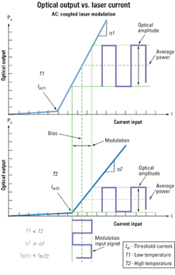
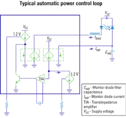
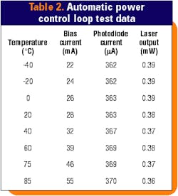
Laser diodes emit coherent light once the laser optical gain has surpassed the mirror loss in the Fabry-Perot (FP) cavity. The current associated with the point of initial coherent light emission is known as the threshold current (Ith). As temperature increases, the optical gain decreases. As the gain decreases, more current is needed for coherent light emission (see Figure 1), and therefore the threshold current increases.The data in Table 2 was obtained using the APC loop of the MAX3863 laser driver and an edge-emitting laser diode. The APC loop maintains the photodiode current by increasing the bias current. The variation is held to only 8 mA over the full temperature range. Photodiode current variations of 8 mA would account for <1% variation in the average power; however, the data in Table 2 shows a larger variation. That's because the measured average optical power variation is more than just a factor of the photodiode current variation.
Increased variation in the measured average optical power is caused by changes in photodiode responsivity, laser-to-monitor coupling, and laser-to-fiber coupling. Compensating for these factors is difficult since they do not always behave in the same way for each laser or setup. For instance, the coupling from the laser to the fiber could increase or decrease with temperature. Even with these external factors, the measured average optical power was well maintained by the APC loop.
Once the laser is biased above the threshold, the ratio of the optical output to laser current is defined as the slope efficiency (η). The slope efficiency of an edge-emitting laser or VCSEL will commonly decrease with increased temperature (see Figure 1). Assuming the average power is held constant, more modulation current is needed to maintain the same optical output amplitude as h decreases. This also affects the extinction ratio since re = 10*log(P1/P0) (dB), where P1-P0 is the optical amplitude and P1 and P0 are the optical powers for a logic 1 and logic 0, respectively.
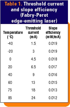
The change in slope efficiency shown in Table 1 can easily cause the extinction ratio to vary by 4 dB or more from -40° to +85°C (assuming the average power is held constant). These large changes in extinction ratio can cause considerable variations in the system's bit-error ratio (BER) over the specified temperature range.2 Given the large variations (and the corresponding degradation in BER), the extinction ratio must be set at undesirably large values at nominal temperature to meet specification over the full temperature range.
In practice, obtaining a large extinction ratio is also difficult due to relaxation oscillation, increased jitter, and the power limits of the lasers. The increased jitter associated with large extinction ratios can also decrease eye openings and the overall system BER performance. Applying compensation, the extinction ratio can be held at an optimal operating level over the entire temperature range.
Just as with average power compensation, a closed and open loop implementation may be used to minimize variations in extinction ratio for changes in laser slope efficiency. Let's look at two compensation methods: K-factor (patent pending) and digital-resistor compensation.
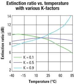
A new feature designed into certain laser drivers is K-factor compensation. This feature increases the modulation current in proportion to the bias current increase. As the bias current is increased by the APC loop (to maintain average power), a portion of the bias current increase is added to the set modulation current.3 Therefore, the total (IMOD) is equal to a predetermined set modulation current (IMODS) plus K times the bias current (IBIAS). The value of K is set on the driver using a single external resistor:Since the modulation current increases as IBIAS increases, the extinction ratio will be compensated over the temperature and life of the laser. Using the values for (IBIAS, average power, and slope efficiency shown in Tables 1 and 2, the extinction ratio for various K values was calculated and is seen in Figure 3. By choosing the K value correctly, the total re variation can be calculated to be <1 dB.
Digital variable resistors can also be used to maintain re. Digital-resistor implementations have the disadvantage of being open loop but offer the possibility of maintaining re within tighter margins. Some digital resistors, for example, feature a temperature-controlled look-up table. Resistor values as a function of temperature are stored in nonvolatile memory with a new memory location allocated for every 2°C temperature increment in the -40° to +95°C temperature range. Using an on-chip temperature sensor, the resistor settings are automatically adjusted as the temperature changes.When the re has reached a predefined minimum value at a given temperature, the digital resistor would be set to decrease the resistance seen by the modulation-setting pin of the laser driver. The decrease in resistance causes an increase in modulation current. Since the change in resistance is a discrete step, re would step to a new value corresponding to the new modulation current setting and new extinction ratio.
Minimizing re variation with digital resistors is limited to the horizontal temperature resolution and vertical resistance resolution of the resistor, but the accuracy is generally very good in most applications. Extinction ratio variations <0.4 dB over the full temperature range can be obtained when using digital resistors and multiple calibration points.
Combining the K-factor and digital-resistor compensation methods, variations in re can be greatly minimized. K-factor compensation can reduce the variation of re. The digital potentiometer can then flatten out the overall response.
An SFF transmitter reference design4 is used to show measured results using the compensation methods described above. The K-factor was chosen to provide about half the compensation and help reduce the slope of re variation. The DS1847 digital resistor was then used to provide additional modulation current compensation using multiple calibration points.
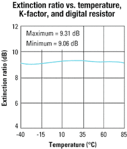
Average power was maintained using the APC loop of the MAX3863. The digital resistor was also connected to the APC loop-setting resistor and was used to correct for vertical offsets in average power due to variations in photodiode current. The extinction ratio was then measured in 5∞C increments (see Figure 4). The measured variation was only 0.25 dB over the entire temperature range using the K-factor and digital-resistor compensation methods.Obtaining results with 0.25-dB variation is excellent, but detailed information about each laser and multiple calibration points are needed. Ideally, a manufacturer that produces large quantities would like to use only one calibration point (room temperature) and one curve in the digital look-up table. While that speeds production and reduces cost, larger variations in re would be expected.
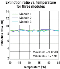
To illustrate this point, the variation of three additional SFF boards was measured. The same K value and digital pot settings were used for all three SFF modules. Each of the SFF boards was calibrated at room temperature to remove offsets in monitor diode current and slope efficiency. During calibration, the digital look-up table values for the modulation current were vertically offset to obtain an operating extinction ratio of 9 dB for each of the SFF boards at 25°C.
The extinction ratio for each of the boards was then measured in 5°C increments as before. The variation is larger than that previously measured on a single SFF board (see Figure 5), but the 0.65-dB variation is still excellent given the many part-to-part variations and the single-point calibration method that was used. Using a parallel resistor with digital resistor, a different K-factor and more calibration points would improve these results even further.The temperature-dependent variables in an optical module can cause large variations in the extinction ratio and average power, which can lead to poor module performance at elevated temperature. Use of the methods described here minimizes the variations of these parameters.
Using the K-factor alone allows for easy setups and good compensation using a closed loop. Digital resistors have the disadvantage of being open loop but offer better temperature compensation. Part-to-part calibration at the production level is also simplified with the digital resistor. Combining the K-factor and digital resistor produces a system with excellent temperature compensation, easy part-to-part calibration, and stable performance.
Craig Lyon is a fiber/high-frequency applications engineer at Maxim Integrated Products (Sunnyvale, CA). He can be reached at [email protected].
- Application sheet: "Modulating VCSELs," Honeywell, February 1998.
- Application note: "Extinction Ratio and Power Penalty," HFAN 02.2.0, Maxim Integrated Products, May 2001.
- Application note: "Maintaining the Extinction Ratio of Optical Transmitters using K-Factor Control," HFAN 02.2.1, May 2002.
- Reference design: "2.5Gbps SFF Transmitter," HFRD 02.0, Maxim Integrated Products, April 2002.
