Methodologies for improving the accuracy and repeatability of SONET OC-48 jitter measurements
New techniques enable the jitter contributed by the test equipment and the fiber-optic transceiver module to be independently determined.
By JIM PRETTYLEAF
Ignis Optics
The performance of small form-factor pluggable (SFP) fiber-optic transceiver modules has improved to the point where these miniature hybrid optical transmit receive modules are rivaling the performance of the test equipment that is used to measure their performance. This is especially true when attempting to measure the deterministic and random phase noise (jitter) of the latest generation OC-48 (2.5 Gbits/sec) SFP fiber-optic transceiver modules.
Standardized measurement techniques that improve the repeatability and accuracy of fiber-optic transceiver module jitter measurements are desperately needed for today's OC-48 systems and for future OC-192 (10-Gbits/sec) and 10-Gigabit Ethernet applications.
Sampling limitations
The first step toward improving accuracy and repeatability of fiber-optic module jitter measurements is to realize that OC-48 test equipment and signal sources are not noise free and will have an impact on the measured results. For instance, when any differential electrical signal source is connected to the input of the fiber-optic module's transmitter, it is critical to initially determine how much random and deterministic jitter these electrical signal sources are contributing.
Experience has shown that the jitter contributed by signal sources, such as stand-alone pattern generators--the pattern generators embedded in a bit-error ratio test sets (BERTs)--or the output of serializer chips, is significant at OC-48 rates and must be accurately measured.
The next thing to keep in mind is that the best digital sampling oscilloscopes cannot directly measure the total jitter (TJ) of a serial data stream to an acceptable probability of error in a reasonable time interval. The following discussions will elaborate on why sampling oscilloscopes will not directly measure the TJ of serial data that contains a mixture of deterministic jitter (DJ) and random jitter (RJ) at error probabilities as mundane as a bit-error-ratio (BER) of 1x10⁻⁹.
Fortunately the root mean squared (rms) jitter ( σ ) quickly converges to a stable value within a short time interval when measured with a sampling oscilloscope. However, at industry-accepted probabilities of error (BER), the measured peak-to-peak value obtained from a histogram measurement is an apparent total jitter (ATJ) that continues to slowly increase as the measurement time interval increases.
This direct measurement uncertainty occurs because the random component of the phase noise deviation is unbounded, resulting in a statistically low probability that the least-likely large-amplitude phase noise deviation will be coincident with the sample time of the oscilloscope. A reasonably good approximation of the total peak-to-peak (p-p) jitter can be calculated from digital sampling scope measurements if the random phase noise (jitter) has a Gaussian distribution.
The following histogram measurement characteristics were observed when using the Agilent 86100A Data Communication Analyzer (DCA), but similar characteristics have also been observed when using digital sampling oscilloscopes from other manufacturers. The time required to collect 1,000 samples (hits) in the histogram window was observed to change as function of:
1. Time/division scale
2. Histogram window height
3. Magnitude of the jitter
The sampling oscilloscope can directly measure the total p-p jitter associated with transporting a small number of error-free bits. For instance the Agilent DCA will directly measure the jitter associated with transmission of 1x10³ error-free bits at BER < 1x10⁻³ in roughly nine seconds, but to do so the scope must measure 1x10³ hits in the histogram window.
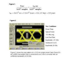
To directly determine how large TJ will be if 1x1012 bits were transported error free, the sampling scope would need to capture 1x10¹² hits in the histogram window. The proportion in Figure 1 shows that if the sampling oscilloscope can measure 1000 histogram hits in nine seconds, an impractical time interval tM is required to directly measure the jitter associated with error-free transport of 1012 bits at a BER < 1x10-12.
The proportion in Figure 1 can be also be solved to show that when using the Agilent's 86100A DCA which is capable of measuring 1000 histogram window hits in nine seconds that a direct measurement at BER < 1x10⁻⁹ would require a measurement time interval of 2500 hours. The resulting conclusion is that sampling oscilloscopes cannot directly provide TJ measurements at bit-error-ratios as mundane as 1x10⁻⁹.
Not noiseless
Optical-to-electrical (OE) converters from different manufacturers are not likely to use detectors and amplifiers with identical gain, bandwidth, and noise characteristics. A simple single-variable experiment that uses the same laser transmitter, the same optical fibers, and the same optical losses with two different OE converters can be used to quickly confirm the differences between optical measurement systems from different manufacturers.
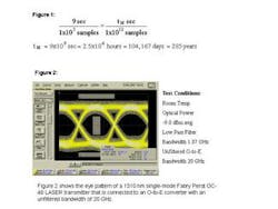
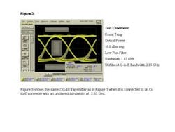
In fact, OE converters with different measurement bandwidths from the same manufacture can quickly be evaluated and shown to contribute different amounts of amplitude and phase noise when using the same laser source and optical fiber losses. Figure 2 shows the eye pattern of a 1310-nm single-mode Fabry Perot OC-48 laser transmitter connected to an OE converter with an unfiltered bandwidth of 20 GHz. Figure 3 shows the same OC-48 transmitter when it is connected to an OE converter with an unfiltered bandwidth of 2.85 GHz.
The optical losses and fiber-optic interconnections for the test results shown in Figures 2 and 3 are identical, so the optical power applied to the high-bandwidth and low-bandwidth OE converters was set to -9.0 dBm average for both measurements. Fourth-order low-pass filters were used to restrict the measurement bandwidth to 1.87 GHz for both eye mask margin tests as required by the Telcordia GR-253-CORE standard. However, the high-speed detector and amplifier in the OE converter with the 20-GHz unfiltered bandwidth provided a measured result that contains significantly larger amounts of test system contributed amplitude and phase noise.
Dedicated SONET jitter test systems
Simple signal sources and OE converters have been observed to contribute significant error when measuring the jitter of OC-48 components. If relatively simple test equipment can contribute significant amounts of phase noise to 2.48830-Gbits/sec measurements, it should be no surprise that the complex dedicated SONET jitter measurement systems that use embedded OE converters and laser transmitters will contribute significant amounts of error when testing the jitter contributed by OC-48 fiber-optic transceiver modules.
A repeatable methodology for obtaining a first-order approximation of the intrinsic phase noise contributed by the dedicated SONET jitter test system is described in an in-depth white paper (see author's biography at the end of this article). To understand jitter contributed by small form-factor pluggable (SFP) OC-48 fiber-optic transceiver modules, the jitter contributed by the test system must first be understood.
The measurement methods described in the in-depth paper have been demonstrated to provide consistent repeatable SONET OC-48 jitter measurements. The techniques described in this paper enable the jitter contributed by the test equipment and the fiber-optic transceiver module to be independently determined.
Once the jitter contributed by the test-set and the SFP fiber-optic transceiver module is known, the SFP fiber-optic transceiver module can be plugged into a complete communication system, and the dedicated SONET jitter tester can be used investigate the incremental jitter that is contributed by the following system-level components:
1. Phase noise from the system's reference clock oscillator
2. Group delay dispersion of printed circuit transmission lines
3. Common mode noise interference from the host system
4. Power supply noise of the host system
Work is underway to further improve measurement repeatability and accuracy by investigating the complex phase noise spectrum of dedicated SONET jitter test systems and their related measurements.
Jim Prettyleaf is senior application engineer at Ignis Optics (www.ignisoptics.com), headquartered in San Jose, CA. A more in-depth white paper on this topic can be found on the Ignis Optics website.
References:
1. Application Note 1267; titled "Frequency agile jitter measurement system"; Agilent publication number 5963-5353E (04/95).2. Product Note; titled "Jitter measurement on OC-48 optical transceivers using the OmniBER 718 or OmniBER 725"; Agilent publication number 5988-5106EN (3 April 2002).3. "Understanding Jitter Measurements and Standards" First Edition; Agilent publication number 5988-6254EN; (June 1, 2002).4. White Paper; "Understanding OmniBER 718 Option 210"; located at Agilent's web site: http://www.agilent.com/cm/rdmfg/omniber/718-719-725/5. Accredited Standards Committee NCITS; working draft titled "Fibre Channel--Methodologies for Jitter Specification"; T11.2 / Project 1230 / Rev 10; (June 9, 1999).

