Need for DGE in DWDM systems
Amplifiers used in ultra-long-haul networks will require dynamic gain equalization technologies.
DR. ATUL SRIVASTAVA, Onetta Inc.
Optical channels in advanced DWDM networks need power equalization to provide acceptable optical signal-to-noise ratios (OSNRs) for all channels. The power of optical channels in WDM systems is not equalized, because of the wavelength dependence of the gain or loss of erbium-doped fiber amplifiers (EDFAs), transmission fiber, dispersion compensators, and other optical elements in fiber-optic transmission systems.
This problem is even more critical in ultra-long-haul (ULH) networks, where signals may pass through up to 50 EDFAs without electrical regeneration. Therefore, next-generation EDFAs will require some method of dynamic gain equalization (DGE).
An EDFA, like a laser, exploits the phenomenon of light amplification by stimulated emission of radiation as predicted by Albert Einstein in 1917. Einstein theorized that if a photon interacts with an excited electron, and if that photon's energy equals the difference in energy between the electron's excited state and its ground state, then the electron will relax into its ground state and emit a new photon with the same wavelength and direction as the original photon. The original photon will continue on its path undisturbed, accompanied by a clone of itself.
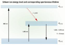
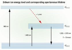
Figure 1, an energy-level diagram of the erbium atom, shows the physical basis for stimulated emission in an EDFA. A pump laser, typically a semiconductor laser emitting at either 1,480 or 980 nm, excites electrons in erbium atoms to a higher energy level. The 1,480-nm laser excites electrons directly to a metastable level, where they reside for a period known as the spontaneous lifetime, before relaxing into the ground state. The spontaneous lifetime at the metastable level is relatively long, about 10 msec. The 980-nm laser, on the other hand, stimulates the electrons into an even higher energy level, where they remain for only a microsecond or so before falling into the metastable level. The erbium atoms in EDFAs reside in a glass host, an amorphous material that preserves most of the dynamics of the erbium energy states while also spreading out the energy levels.
Amplification occurs when a signal photon enters the EDFA and stimulates an erbium electron occupying the metastable energy level. The excited electron falls back into its ground state and emits a photon with the same wavelength and direction as the signal photon. In this way, one photon becomes two. Subsequently, each of those two photons stimulates excited electrons downstream, resulting in four photons, and so forth. In this way, the EDFA amplifies the incoming signal. Key to the process is that photons with optimal wavelengths for singlemode glass optical fibers have an energy that happens to equal the difference in energy between two states of an erbium atom.Figure 1. Shown here is the physical basis for stimulated emission in an erbium-doped fiber amplifier (EDFA). A 1,480-nm pump laser excites electrons in erbium atoms to a higher energy level, where they reside for a period known as the spontaneous lifetime (about 10 msec) before relaxing into the ground state. The 980-nm laser stimulates the electrons into an even higher energy level, where they remain for only about a microsecond. The horizontal lines represent subtle variations in the energy levels of erbium atoms caused by differences in their local environments within the silicon dioxide fiber. These variations allow the EDFA to amplify a bandwidth of frequencies-about 1,520-1,620 nm-and thereby render them suitable for DWDM applications.
A single isolated erbium atom has clearly defined, discrete energy levels. Figure 1 shows not one, but several horizontal lines within each energy level. These lines represent subtle variations in the energy levels of erbium atoms caused by differences in their local environments within the silica dioxide fiber. These variations allow the EDFA to amplify a bandwidth of frequencies-about 1,520-1,620 nm- and thereby render them suitable for DWDM applications.
Although the EDFA will amplify photons throughout this bandwidth, the cross section for stimulated emission (i.e., the probability that an incoming signal photon will actually stimulate an excited erbium electron) depends on the wavelength of the photon. In silica glass, photons with wavelengths around 1,530 nm have the highest probability of being amplified. This wavelength-dependent probability of amplification explains why EDFAs have non-uniform gain across their bandwidth.
An EDFA's gain uniformity is a function of its input power. At low input powers, the gain peaks between 1,530 and 1,535 nm and plateaus between 1,540 and 1,560 nm. The difference in gain between the peak and plateau can exceed 10 dB. At higher input powers, the EDFA's gain is less non-uniform.
Manufacturers of wideband EDFAs insert static gain equalization filters (GEFs) between the stages of an EDFA to flatten the gain spectrum. The most successful GEFs, based on thin-film technology, consist of translucent multilayer structures of materials with different indices of refraction that create interference ef fects. The interference effects compensate for the wavelength-dependent gain of the EDFA by diminishing transmission for the high-gain wavelengths.
The ideal GEF would have a transmission spectrum that is an inverse of the EDFA's gain spectrum. According to the principles of Fourier, the desired transmission spectrum is a complex curve that transforms and can be duplicated by adding a number of sine waves. The various layers of the GEF produce sinusoidal variations of transmission with wavelength, which add to create the final result.
Despite the sophisticated thin-film technology of the GEFs, these devices do not compensate with complete success, leaving the power of the various channels somewhat unequal. Therefore, the gain spectrum of the integrated EDFA and GEF subsystem still has peaks and valleys. The ripple-the difference between the highest peak and lowest valley-is still typically about 1 dB.
A ripple of 1 dB in channel powers may be tolerable for a transmission system, but the ripple will increase as the signals propagate through a cascade of EDFAs integrated with GEF units. The ripple increases because different GEFs manufactured in the same batch tend to generate peaks and valleys at the same wavelengths. The systematic error introduced at each transmission span compounds throughout the network.
Another problem is that engineers have to custom-design and prototype a GEF for each EDFA design, which increases development time and affects the overall system cost.
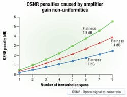
Figure 2 shows how the OSNR penalty increases as a nonlinear function of the number of transmission spans for three cases: a ripple (flatness) of 1, 1.4, and 1.8 dB. The variations in signal strength may exceed the system margin and begin to increase the bit-error rate (BER) if the OSNR penalty exceeds 5 dB. When the gain spectrum starts with flatness of 1.8 dB, the OSNR penalty degrades by more than 5 dB after only eight transmission spans. The gain non-uniformity not only can lower the signal strength, but also can raise the power of certain channels above the maximum recommended, making other channels susceptible to nonlinear optical effects such as four-wave mixing.
This OSNR penalty limits the reach of DWDM line systems and requires signal regenerators at intervals of approximately 500 km. These expensive devices convert the signals from the optical domain to the electrical domain, typically reshaping, retiming, and re-amplifying the signal before triggering lasers to convert the signal back from the electrical domain to the optical domain. In ULH networks, carriers would like to increase the spacing between regenerators to 1,000 km or more, in which case the signal would have to pass through up to 50 amplifiers without electrical regeneration. Therefore, these networks require EDFAs with excellent gain uniformity.
Another problem is that the gain uniformity diminishes when input power levels diminish. The GEFs are optimized to flatten the gain spectrum of a fully loaded EDFA. But if a carrier wants to operate the system with fewer channels (i.e., to reconfigure it dynamically), then the lower input power can decrease the EDFA's gain uniformity, thereby impairing the effectiveness of the GEF and increasing ripple in the network.Furthermore, the use of only a few channels can cause a phenomenon known as "spectral hole burning," which actually changes the gain spectrum of the EDFA by creating a gain dip in the region of the active channel. Spectral hole burning can create a gain spectrum for which the GEF was not optimized, making gain flattening very difficult.
For all these reasons, future ULH, dynamically reconfigurable networks will require EDFAs with DGE or some other technology to equalize the EDFA's wavelength-dependent gain.
A technology for DGE could offer the following benefits:
- Enable longer amplifier cascades in ULH networks in which the signal has to pass through as many as 50 EDFAs without electrical regeneration. Similarly, DGE technologies could facilitate efficient distributed amplification to outweigh high passive losses of modern metropolitan and regional DWDM applications.
- Support dynamic network reconfiguration by making it possible to load only a few channels without paying a penalty in OSNR.
- Make it possible to use generic rather than custom-designed GEFs, thereby shortening time-to-market and reducing development costs.
- Adjust the gain tilt of EDFAs in response to changes in input power, thereby making it possible to eliminate the variable optical attenuators (VOAs), which perform this function today.
- Eliminate the need for cleanup filters in ULH systems. In submarine DWDM systems, special cleanup filters, separated by several EDFAs throughout the chain, remove residual ripple from the GEF-filtered EDFA gain spectrum. ULH terrestrial DWDM systems would also require these cleanup filters. DGE would render these filters unnecessary in both submarine and terrestrial systems.
A DGE technology could work on each channel individually or on several channels at once. It could work on many individual channels or groups of channels in parallel, or it could work in series, as a concatenation of lumped filters.
A conceptually simple but expensive approach is to send the channels through a demultiplexer, measure the power of each channel with an optical channel monitor, then equalize the power by diminishing the power in all the channels except the weakest one with a set of electronically controlled optical attenuators. An acousto-optic technique could re place the demultiplexer and motorized VOAs, but it would raise several other issues like physical robustness and vulnerability to frequency interference. Another possibility is to introduce a diffraction element that diverts the individual channels onto an array of micro-electromechanical system (MEMS) de vices with voltage-dependent reflectivity. Other gain equalization techniques can be imagined based on waveguides or liquid crystals.
The best solution is an intelligent filter integrated with a monitor that measures the input power in each channel and feeds forward an electronic signal to change the characteristics of the filter. This type of filter would enable network service providers to create dynamically reconfigurable ULH networks.
Dr. Atul Srivastava is chief scientist at Onetta Inc. (San Jose, CA).


