Raman components gain some new requirements
Despite using components similar to those used in EDFAs, Raman amplifiers increase the power-handling requirement of passive devices along with creating other demands.
DR. BOB SHINE and DR. JERRY BAUTISTA, WaveSplitter Technologies Inc.
One promise of the all-optical network is that it will allow carriers to reduce network costs while significantly increasing bandwidth capacity. A step toward achieving this promise is amplification technologies that enable the transmission of optical signals over distances greater than 3,000 km, removing the current need for electrical regenerators every 400 km in long-haul transmission systems.
A key technology for ultra-long-haul systems since its distributed amplification can significantly improve the signal-to-noise performance of the system is Raman amplification. While observation of the Raman effect in fibers predated erbium-doped fiber amplifiers (EDFAs), most people are more familiar with EDFAs.1 The signal-to-noise improvement of Raman amplifiers is also critical to achieving ultra-high bit-rate systems where additional performance requirements are placed on the system due to dispersion impairments. Not surprisingly, the Raman amplifier market is forecast at more than $1 billion within just a few years.
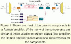
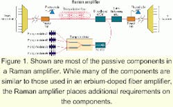
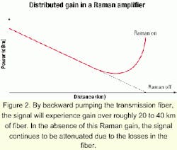
Unlike an EDFA, where a section of specialty-doped fiber creates amplification when pumped, the transmission fiber itself becomes the amplifier medium in a Raman amplifier. In the Raman process, gain is created due to the conversion of the pump photon to the signal photon, with the simultaneous production of an optical phonon, a process called "stimulated scattering." Since this is a nonlinear process, high pump powers are required, typically in excess of 700 mW.As shown in Figure 1, the Raman pump power is typically transmitted backwards, or in the opposite direction of the signal transmission. Since the pump power is attenuated along the length of the transmission fiber, the signal will experience gain only over the last 20 to 40 km of the transmission link. Because of the distributed gain, lower local power levels are needed over the transmission length, greatly reducing fiber nonlinearities such as four-wave mixing (see Figure 2). This distributed gain results in an improved signal-to-noise performance, enabling ultra-long-haul and high-bit-rate applications.2, 3
While the gain wavelengths of an EDFA are determined by the energy level of the erbium ions-typically covering 1,530 to 1,610 nm for the C- and L-band amplifiers-wavelengths over which the amplification takes place in a Raman amplifier depends on the pump wavelength and the fiber material. For silica fiber, gain occurs roughly 100 nm from the pump wavelength, so to amplify signals at 1,550 nm, a pump wavelength around 1,450 nm is used. Different pump wavelengths allow gain to occur at new wavelength windows, opening up new amplification windows for the future. The gain bandwidth is roughly 20-30 nm wide, similar to the peak of the erbium spectrum. By using multiple pump wavelengths, the Raman gain can be shaped to provide a wide, flat-gain profile in the desired wavelength band.
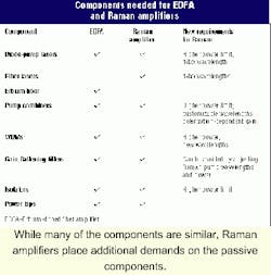
While the benefits of Raman amplifiers are clear, this amplification method places additional demands on the amplifier components. The Table highlights some of the common components for both EDFA and Raman amplifiers and identifies the new requirements placed on the components of the Raman amplifiers. Many of the passive optical components require higher power-handling capability in the Raman devices.
While average EDFAs typically require a pump power of 300 mW or less, Raman amplifiers operate with a pump power typically in excess of 700 mW and sometimes at levels greater than 1 W. Although, the power-handling capability of passive optical components has been increasing to meet the need of higher-channel-count DWDM systems, Raman amplifiers represent a significant increase. While the power taps and WDM components will experience high power levels, the component that will gain the most optical power is the pump combiner. This component is used to combine multiple pump lasers to achieve the high power required for Raman amplification.Both micro-optic and fused-fiber components can be used as a pump combiner. In these devices, the power from different pump lasers at different wavelengths is combined into a single output fiber.
The micro-optic de vices work by using a thin-film filter that reflects one wavelength while transmitting a second wavelength. The micro-optic components-the fiber, collimating lens, and filter-are carefully aligned and fixed in place, typically using an epoxy.
In a fused-fiber pump combiner, the two wavelengths always remain in the fiber. The combination of the two wavelengths occurs in the fused region where one wavelength is coupled across into the second fiber. The fused-fiber device combines two separate wavelengths due to the differential coupling in the long fused region, a result of the different modal overlaps for the separate wavelengths. For high-power handling, it is expected that the fused fiber will offer better performance, since the power is always contained in the fiber, while in micro-optic devices, the interface region raises concerns due to contamination that may limit the power-handling capability of these devices.
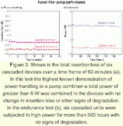
Short-term and long-term reliability testing was performed to investigate the power-handling capability of a fused-fiber pump-laser combiner. The test lasers were Raman fiber lasers operating at 1,455 and 1,480 nm, each providing greater than 1.5 W. A single device was subjected to high power to identify possible failure modes. After the single device was successfully tested, a series of six cascaded devices were subjected to the high power to allow observation of a greater number of units.
The first test consisted of subjecting the fused-fiber devices to the highest possible input power available. In this test, each of the two lasers was run at greater than 3 W, for a combined power of more than 6 W in the pump combiners. This test was only run for 60 minutes since the lasers were operating above their rated power. Figure 3a shows the measured insertion loss of the cascaded devices during the test. The devices showed no change in performance even when subjected to 6 W of input power, the highest known power level used with a pump-laser combiner.An endurance test was also performed on the fused-fiber pump-laser combiners. In this test, the two lasers were run at their rated power level of 1.5 W. The test was conducted over 500 hours, and again, no change in performance was observed during the test (see Figure 3b). After the test, each device was inspected; no change in the insertion loss of the individual devices was found. While the power-handling of micro-optic devices is improving, screening to ensure performance at high power will likely be required. That will ensure there is no contamination at the free-space interfaces and that no contamination occurred during manufacture. With the fused-fiber devices, the power always remains in the fiber, ensuring high-power performance by design.
In addition to the increased power-handling capability necessary for passive optical components, Raman amplifiers require components to cover a range of wavelengths. While the pump bands for an EDFA are fixed within either the 980-nm or 1,480-nm bands, the Raman gain wavelength depends on the pump wavelength. Often, a number of different pump wavelengths are used to create a broad, flat Raman gain profile. Unlike an EDFA, where a gain-flattening filter is used to equalize the gain for different wavelengths due to the spectrum of the erbium gain, the gain flatness of the Raman amplifier is adjusted by changing the pump wavelengths and individual pump powers.
To determine the optimum pump wavelengths for a system under design, several different wavelength plans are tested at the prototype phase. For this reason, Raman components must be able to rapidly address new wavelengths. Micro-optic pump combiners and WDMs can address this need but may require new coating runs for new pump wavelengths under development. The wavelength performance of a fused-fiber pump combiner is determined during the fusion process, facilitating rapid turnaround of new wavelengths.One other key distinction between EDFAs and Raman amplifiers is the polarization-dependent gain of the amplification process. In an EDFA, the polarization dependence is minimal, and no special precautions are usually taken to ensure the orientation of either the pump or signal polarization. The Raman gain, however, is polarization-dependent. To minimize polarization-dependent gain, either the input polarization from the pump lasers must be scrambled or two orthogonal polarizations at the same wavelength must be combined. The latter function can be performed with a polarization beam combiner. Unlike the pump combiners, where different wavelengths were combined, a polarization beam combiner combines two pump lasers at the same wavelength but with orthogonal polarization. Again, both micro-optic and fused-fiber devices can be used to perform this function, with a similar benefit in power-handling anticipated for fused-fiber devices.
While there are a number of differences between EDFA and Raman amplifiers, EDFA trends can point to the future requirements of passive components for Raman amplifiers. Higher amplifier powers will be needed to enable higher-channel-count, longer-distance, and higher-bit-rate DWDM systems. Integration of functions will also occur, as happened with EDFA components. In addition, space continues to be at a premium, requiring smaller passive components. Ideally, a Raman amplifier and EDFA would occupy the same space previously occupied by just the EDFA.
Finally, wider amplifier bands will be needed. While the EDFA is limited to the erbium spectrum, Raman amplifiers will open up new amplifier windows such as the S+ and S-band from 1,450 to 1,520 nm, requiring components to operate at these wavelengths.
Raman amplifiers are a critical technology to enable both ultra-long-haul and high-bit-rate systems. While Raman amplifiers place additional demands on passive components, these demands can be met by today's technologies. In particular, fused-fiber devices have been shown to handle power in excess of 6 W and can meet the wavelength flexibility needed to optimize the Raman gain. With additional products to enable the technology, such as polarization beam combiners, the market for Raman amplifiers will indeed meet analysts' forecasts.
Bob Shine, Ph.D., is director of marketing and Jerry Bautista, Ph.D., is the chief technology officer and senior vice president of technology at WaveSplitter Technologies (Fremont, CA).
- R.H. Stolen and E.P. Ippen, Applied Physics Letters, 22, p. 276 (1973).
- L.D. Garrett, M. Eiselt, R.W. Tkach, V. Dominic, R. Waarts, D. Giltner, and D. Mehuys, Proceedings of Optical Fiber Conference 2000, paper PD42, Baltimore, MD (March 2000).
- O. Gautheron et al., Proceeding of the Optical Fiber Conference 2000, paper TuJ4, Baltimore, MD (March 2000).
