Need for accurate measurements amplified as wavelengths increase
An influx of high-power optics is driving the push for optical spectrum analyzers with more powerful performance.
GRAHAM SPERRIN, Anritsu Co.
Today, DWDM is widely deployed, but the push toward even more channels and alternative types of broadband optical amplification is stretching the boundaries of optical fiber. Additional channels in the C-band (1530-1565 nm) and L-band (1565-1625 nm) are significantly increasing the levels of total optical power on a conventional single fiber. As a result, optical fiber is quickly reaching its limits in capacity, safety, and nonlinear effects.
DWDM not only increased the potential capacity of fiber, it created a demand for optical test instrumentation with higher performance. Higher bandwidth reduces the margin for error and increases the types of measurements that need to be made. Fortunately, advances in test instrumentation have led to equipment with the performance necessary to satisfy these complicated measurement requirements.
What are the technologies that require test equipment to offer higher performance? Traditionally, erbium-doped fiber amplifiers (EDFAs) have been deployed in both undersea and terrestrial optical networks because they offer optical amplification in a defined wavelength range. Initially designed for use in the C-band, EDFAs now also support the L-band. But optical fiber offers more than the C- and L-bands, which is driving the development of alternative amplifiers.
Raman amplification not only covers the C- and L-bands, it has the capability of being extended into the S-band (1460-1530 nm) when appropriate laser pumps are applied. This amplification opens up the true bandwidth capacity of fiber. Long term, the view is that Raman amplifiers will replace the EDFAs. Initially, both fixed gain blocks and distributive amplifiers are likely to be deployed alongside EDFAs.The basis of Raman amplification is a process called nonlinear stimulated Raman scattering, which is a scattering of light by molecules. Scattered light is shifted from the incoming light by a frequency characteristic of the molecules. Raman amplification occurs when a sufficiently large pump signal is launched into a fiber at a lower wavelength than the signal to be amplified. Amplification occurs when the pump photon gives up its energy for more photons at the signal wavelength. The Raman gain depends strongly on the pump power and the wavelength offset between the pump and signal. Raman amplification comes in two packages: distributive gain where a fiber is pumped either in its entirety or partial length or in fixed gain blocks.
Raman amplification occurs because of the intrinsic properties of silica fiber when pumped at high power, usually 100 nm below the transmission amplification window. Raman gain increases almost linearly with wavelength offset between signal and pump, peaking at approximately 100 nm, then dropping rapidly with increased offset. Conventional fibers provide Raman gain but the amount of gain is different for each fiber, so proper pump-laser selection and setting is necessary. To cover the C- and L-band window, it is necessary to have as many as seven pump wavelengths, each adding higher power to the fiber. Each pump contributes to a usable gain window within the C- and L-band of 48 nm. The combination of these pumps adds more power to a single fiber.
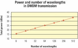
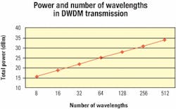
This increasing power in a single fiber, and the progression into alternative wavelength bands, is placing greater demands on the performance and test requirements of optical instrumentation. One solution introduced in recent years is new types of fiber to meet the demands of such high powers. Subsequently, power levels ranging from 23 to 30 dBm need to be measured with confidence. Measurements in the extended wavelength bands require performance comparable to those of the C-band.The C-band is running out of available channels even with the use of tighter channel spacing. That's pushing other transmission windows such as the L-band. With higher transmission rates such as 10 and 40 Gbits/sec, there are restrictions on the channel separation, resulting in the need for greater wavelength coverage. Minimum channel spacing must strike a balance between transmission rates and wider wavelength coverage to meet capacity requirements, which is another reason high-power measurements are needed. On the assumption that the power required for one wavelength is 7 dBm (immediately after amplification), the total power required for 64 wavelengths exceeds 25 dBm. If 100 to 200 wavelengths are used in the future, as expected, then power measurements of 30 dBm will certainly be required (see Figure 1).
In a Raman amplifier, an optical DWDM channel interacts coherently with the silica molecules of an optical fiber that is excited by a high-power laser pump of 220-300 mW, resulting in optical gain in the DWDM signals. When multiple pumping is applied for extended gain window, care is required because of pump depletion where power is transferred from the lower wavelengths to higher wavelengths.
Despite years of laboratory work, acceptance of Raman amplification for deployment has been slow. However, the development of counter-propagating Raman pumps is making Raman amplification more efficient as an amplifying technique. For this configuration, the Raman pump is fed from the end of a span, or length of fiber, where the signal power is lower. That allows Raman gain to build up without saturating the amplifier; much less pump power is then required for a higher gain. In distributed Raman amplified networks, the pump light is launched into the fiber at inline amplified sites opposite to the direction of the signal. Thus, Raman amplification acts as a low noise preamplifier for repeatered (i.e., EDFA) and non-repeatered networks.
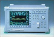
With the advances in high-data-rate systems (10 and 40 Gbits/sec), it is clear system noise will limit 40-Gbit/sec networks and restrict the spans to 40 km. To make such systems economically viable, some 80-km spans are needed. Raman amplification with EDFAs will help to achieve a solution for 40-Gbit/sec implementations and cost-viable networks.Test instrumentation has also evolved to test the high power associated with Raman or similar amplifiers for multiple bands and high data rates. Advances in optical spectrum analyzers (OSAs) enable these devices to make highly accurate measurements at both the C- and L-bands. To conduct analysis on high-power amplifiers, many OSAs now integrate an internal, reference wavelength source and double-pass diffraction technology, resulting is a single instrument that can conduct high-end analysis of DWDM components and DWDM systems with close channel spacing.
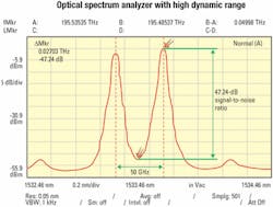
OSAs today also can cover a wide dynamic range-typically 70 dB at 1 nm-which is required to attain an accurate optical-signal-to-noise (OSNR) measurement. In DWDM systems, an OSNR of >45 dB is required at 50-GHz spacing (see Figure 2). OSAs also offer improved resolution (50 pm) and wavelength accuracy (20 pm) in the C- and L-bands, which allows technicians to conduct accurate analysis of optical amplifiers and wideband DWDM networks.
The increasing number of channels and the higher-power optical amplifiers also affect absolute power calibrations. For many years, absolute power calibrations in the range of +5 to -25 dBm were acceptable. Now, however, there is a need for power calibration in the range of 25-35 dBm. That requires National Calibration Laboratories to offer a service to support second-layer calibration laboratories and test equipment manufacturers. Measurement and calibration of high power requires careful consideration, especially with respect to laser safety standards such as the Food and Drug Administration and International Electrotechnical Commission.
The high-power sensors used with optical power meters are based on a low-level sensor that has an attenuator before the detector element, usually in the form of a disc attenuator or an integrating sphere. A single wavelength calibration such as the center wavelength of the transmission window is not sufficient for optical pumps and multiwavelength networks. Multiple-wavelength calibrations of the low-level sensor and attenuation element are necessary to ensure and maintain traceability and adhere to ISO standards. An integration sphere that has an internal surface coated with a highly reflective material to reflect light across a wide wavelength range is ideally suited to conduct high-power measurements such as 35 dBm. These types of high-power measurements are necessary for analysis of Raman amplification and extended DWDM windows.
The integration sphere is calibrated in combination with the low-power sensor across the wavelength range. That allows it to support the out-of-window wavelengths of the optical-amplifier pumps as well as DWDM in the C-, L-, and S-bands. When light from any light source is input to the inside of the integration sphere, it is reflected repeatedly and randomly around the inside of the sphere so that it is completely integrated. The intensity distribution of the light in the sphere is completely uniform around the inner surface.
Effects of the input light beam are such that the angular dependence of the light and reflection are completely averaged with the beam pattern. The input light beam is distributed by the high reflectivity and scattering properties of the coating inside the integration sphere. Due to the repeated and random reflection inside the sphere, a uniform light beam is obtained. The light in the sphere becomes evenly distributed, enabling a high-power beam to be attenuated. A low-level sensor is attached to the sphere to sample 30 dB down on the input light.In addition to the actual power level, the connector type can affect traceability and power accuracy. With the higher powers and high data rates (10 and 40 Gbits/sec), optical return loss is an issue. Typically, an angle physical contact (APC) connector is applied as a result of its 60-dB return loss and physical contact. The power sensor must perform accurate measurements with this connector type. The sensor may be lensed, attenuated, or directed onto a detector of small surface area, which will not provide an accurate measurement. APC connectors can be applied to integration sphere sensors, but calibration is necessary for calibration accuracy and uncertainty for multiple wavelengths.
Return-loss measurements have previously used Fabry-Perot lasers, an approach referred to as continuous-wave (fixed wavelength). It is now necessary to do swept measurements with a line-narrowed source to check return loss across the extended wavelength bands. Swept measurements are possible using a tunable laser with high OSNR, an optical power meter, and a wideband directional coupler that provides 65-dB directivity. To achieve greater measurement range, the tunable laser with high OSNR can be configured with an OSA and directional coupler.
For high-power devices, the end surface of the output connector is usually APC-polished. The reason is that the end surface finish of a physical contact-polished connector is 4% of the transmitted beam (see Figure 3). That returns to the laser device when the connector end is open, which can cause power oscillation and possible damage to the laser device and connector end.
The amount of light returned from the end of a bare fiber varies, depending on the condition of the fiber's end cut. If a large amount of light is returned, then an error may be introduced into the measurement and the user's light source and optical device may be damaged. Care should be taken to avoid such a problem. Special cleaving equipment to reduce the reflection is necessary for devices that may be damaged. Another option is to add an isolator to protect the source.
It is necessary to ensure that people are not exposed to the laser light coming from the end of a bare fiber or an accidentally folded or otherwise damaged part of the fiber. High optical powers can cause eye damage and burn the skin. Therefore, care is required when measuring high powers. Where possible, technicians should bring power sensors to the source instead of taking long fibers to the sensors. When using connectors, it is important to keep the connection couplings clean to avoid burning at the surface of mating devices. Some connector types provide built-in protection flaps for safety and cleanliness.
Increasingly, optical power meters must perform additional measurements due to the influx of high-power optics. An optical system's performance can be degraded by nonlinear effects, which increase proportionately as data rates climb. Nonlinear effects limit overall system performance and the possible span lengths between amplifiers. Large effective area fibers support higher signal powers without distortion, resulting in an improved OSNR compared to conventional fibers.
Nonlinear effects are a result of complex interactions between the optical power in the fiber, DWDM channel spacing, and proximity to the zero dispersion of the fiber. These interactions include four-wave mixing, cross-phase modulation, and self-phase modulation. Each of these ingredients can be measured to determine its potential role in causing nonlinear effects. Chromatic dispersion is measured using traditional phase delay or a multiwavelength optical time-domain reflectometer (OTDR), power is determined using highly accurate power sensors, and the wavelength and channel spacing are measured with the OSA. The overall effect is measured using an OSA or heterodyne technique (optical frequency domain).
To accommodate the high powers associated with multiple DWDMs and optical amplification, there are special fibers that allow for increased power before nonlinear effects occur. That is achieved by increasing the effective area of the fiber that the light sees so that the power light intensity is spread across the fiber face. These fibers offer 30% more effective area than conventional fiber. For example, the high-power fiber provides 72 microns sq compared to conventional non-zero dispersion-shifted fiber's 55 microns sq.
Advances in OTDRs enable these instruments to measure these new fiber types. Available OTDRs can now measure four wavelengths and chromatic dispersion characteristics from one end of an optical fiber. These deinstruments now also offer performance such as high dynamic range of 45 dB and short dead zones of 8 m to conduct measurements on high-power fibers.
The S-band will follow the L-band, but the downturn in the telecommunications business appears to have pushed back implementation by 12-18 months. Research is expected to continue, however. Developers are investigating ultra-large-capacity systems that include the S-band and amplifier hybrids to cover a wider transmission range.
With extended wavelength usage and increases in optical power, the need for test instrumentation with higher accuracy, higher-power measurement capability, and broad optical band performance will become even greater than it is today. Because of these factors, test equipment must support measurements >20 dBm and at the very least offer testing in the C- and L-bands.
Graham Sperrin is a marketing manager for Anritsu Co. (Richardson, TX).


