Passive universal depolarizer spurs Raman revolution
With breakthroughs in new 1400-nm pump and depolarizer technologies, the way is open to wider deployment of Raman products.
GUY SAUVE and BRUNO DION, ITF Optical TechnologiesDepolarizers have attracted a lot of attention in recent months because of their promising applications. Their deployment to date is restricted to niches because of their technical limitations. However, depolarizers have not yet reached their full potential, and a new breakthrough-the passive universal depolarizer-is opening the way to extensive deployment. This new component creates the conditions for simpler, cheaper designs that should propel Raman-amplifier market penetration.
The basic function of a depolarizer is to convert a polarized light input into a randomly polarized output (see Figure 1). Actually, the light is depolarized on average. There is no such thing as depolarized light-at any given moment in time, light always has a state of polarization. The function of a depolarizer is to scramble the polarization so that on average over time, there appears to be no specific polarization state.
General applications
Though the depolarizers will find their main market in Raman designs, which are very sensitive to polarization effects, they are already used for a number of applications outside that field, particularly in the test and measurement market.
The polarization of the light source can cause measurement errors. Though LEDs are perceived as incoherent, the rectangular guiding structures of the diode typically make the output beam partially polarized. A degree of polarization as high as 30% is not uncommon. It can cause non-negligible measurement errors because of the polarization dependency of the DUT.
Inserting a depolarizer at the output of the source reduces the measurement variation. Typical depolarizers targeted at that market feature a degree of polarization (DoP) of 10% over the band of a tunable laser. But because of the high impact of polarization-dependent gain (PDG), the depolarizer has attracted most interest and finds most applications for Raman amplifiers.The stimulated Raman scattering effect is highly dependent on polarization. Since pump-laser diodes have highly polarized outputs, polarization multiplexing with polarization pump combiners (PPCs)-also known as polarization beam combiners-is commonly used in pump lasers to reduce the PDG. Power levels of the pump lasers must be closely controlled, and a low degree of polarization must be maintained to achieve optimum Raman gain and improve gain flatness. Consequently, the number of active and passive components can increase very rapidly.
A first application for the depolarizer is related to the physical properties of the Raman effect. Since that effect is strongly asymmetrical, less power is normally required at the higher wavelengths to get a flat gain curve. There are different solutions to that issue, such as using less power or using longer spacing for the higher-wavelength pumps.
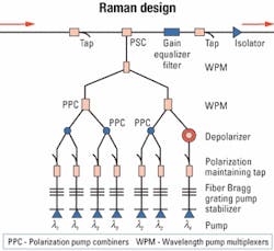
Another way to resolve the problem is by using one pump at the higher wavelengths instead of a pair of pumps (see Figure 2). However, the effect of the PDG means that the single pump must be depolarized. Depolarizers designed for a single pump and with a narrow bandwidth are available on the market.
As for the instrumentation market, narrowband depolarizers have a limited niche market. However, a product supporting the full 1400-nm band for all states of polarization (SoPs) would open exciting new possibilities. The market for depolarizers is currently restrained by technical limitations, not by the range of potential applications. It's worthwhile to take a look at the commercially available depolarizer technologies and their restrictions.
Design approaches
There are various types of depolarizers on the market, the most popular being the Lyot using polarization maintaining (PM) fiber. There are also a number of alternative approaches such as the recirculating ring depolarizer.
These Lyot depolarizers evolved to an all-fiber design. Instead of crystal plates, they use birefringent fibers of different lengths spliced at 45 degrees. If the length of the two pieces of fiber is long enough, the light will be depolarized.
That length is related to the coherence length (Lc) of the light source. Figure 3 shows some typical examples of the spectral profile of three laser sources. The linewidth (and its related Lc) varies significantly. For the sources shown in Figure 3, Lc could vary from 3 mm to 1 km. In addition, some pumps' Lc varies considerably with input power. In practice, the Lyot depolarizers are limited to depolarizing a source of very short Lc (about a few millimeters) and a narrow wavelength range, which considerably limits their potential applications for Raman amplifiers.Another approach is to use a cascade of 2x2 couplers. The incoming light is split into two beams, one of them being recirculated back and coupled with the incoming beam. That recombination scrambles the polarization. By concatenating enough of these couplers, the DoP can be reduced significantly. The effect of concatenating these couplers is to increase the insertion loss, which can be as high as 4 dB. Furthermore, the device is limited to short Lc to prevent the incoming beam from interfering with itself through the loop, and the depolarization of all SoPs cannot be guaranteed. In practice, that solution is not appropriate for Raman designs.
Numerous other technologies have been demonstrated, such as products based on the electro-optic effect or crystal. None of them have enjoyed commercial success so far.
Though there are depolarizers on the market, they all have significant limitations. To get rid of all PPCs in the case of a typical Raman design, for instance, a designer would need six depolarizers, followed by five WPMs (instead of three PPCs and two WPMs), which would not be acceptable. While existing depolarizers are limited to niche markets, the full potential of depolarizers can only be achieved if the bandwidth limit can be lifted and depolarization is guaranteed for all SoPs.
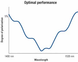
Universal depolarizerA new breed of depolarizers, the universal depolarizer, has been announced recently. Because it is SoP- and wavelength-independent, it opens the way for designs whereby only one depolarizer is needed per amplifier after the pump multiplexing stage. Its other advantages include low insertion loss, a low degree of polarization, and a compact package.This new depolarizer is based on a unique design. The temporal decoherence comes from the differential group delay between the slow and fast axis polarizations. It uses a short singlemode-fiber length with efficiency equivalent to tens of kilometers of PM fiber. Figure 4 shows the simulated performance of the component.
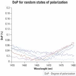
The universal depolarizer will easily accept lasers with Lc 1 m with any SoP at the input. Such sources are already available on the market, and many vendors are working to guarantee stable, short Lc, independent of the input power variations.To demonstrate the tolerance to any SoP and wavelength, a test setup (see Figure 5) was also designed. The results show very little variation in the DoP when the SoP is tested randomly (see Figure 6). The results show a low DoP over 20 nm. These initial prototypes are being improved and a 40-nm band is targeted for the next generation.
Disruptive technology
Raman-amplifier designers are currently trying to reduce their costs. The universal depolarizer can be used in two alternative ways to reach that goal.
One way is reducing the number of pumps per amplifier, which will open the way to cost-effective products. Using these new depolarizers eliminates the need for using two pump-laser diodes per wavelength. As high-power pump-laser diodes are available and getting less expensive, two polarization-combined pumps at the same wavelength can be substituted with a single high-power pump to reduce the number of pumps per amplifier. A single depolarizer can be used at the output of the pump combiners. Another way to reduce cost is by spreading the pumps more evenly over the band to achieve better flatness, eventually eliminating the requirement to use a gain-flattening filter.
Most amplifiers used by carriers today are based on erbium-doped fiber-amplifier (EDFA) design. EDFAs have dominated the field of amplifiers so far, primarily because they feature a power efficiency advantage over Raman. With breakthroughs such as the improving supply of 1400-nm pumps with stable Lc, as well as the universal depolarizer, the way is open to wider deployment of Raman products.
Guy Sauve is marketing director and Bruno Dion is research and development projects director at ITF Optical Technologies (Ville de Saint-Laurent, Quebec).


