Bit-to-the-future: Emerging transport systems and optical-fiber design
Transport cost-per-bit and emerging transmission technologies will largely define vendors' fiber-development strategies.
As high-data-rate networks start to define the competitive communications landscape, network operators seek technologies that enable lowest cost-per-bit optical transmission. But balancing the need to install cutting-edge technology with the desire to maintain a manageable fiber infrastructure is difficult at best.
Many builders install multiple conduits, or ducts, as part of a strategy to support tomorrow's fiber technology. As fiber exhaust is approached, these operators face a critical decision: upgrade with new technology, such as proposed long-band (L-band) 1565- to 1620-nm channels, use higher time-division multiplexing (TDM) rates on the operating fibers, or install a new cable in the next conduit. These "buy versus upgrade" decisions often require as much analysis as the initial "build versus lease" decision.
As optical-network systems evolve, operators will rely on emerging technologies to use more of the available fiber's bandwidth as well as next-generation optical fiber that improves transmission performance. Important technical and economic issues to consider in network migration situations along with some potential avenues for packing more bits onto optical fiber are outlined here.
Optical-fiber choices for long-haul network builders basically fall into two main categories. The first is standard singlemode fiber, also known as nondispersion-shifted fiber (NDSF or ITU G.652). The second type is non-zero dispersion-shifted fiber (NZ-DSF or ITU G.655). Corning commercialized the first NZ-DSF in 1994 with its SMF-LS fiber.
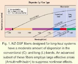
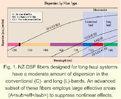
Fibers first evolved from G.652 to dispersion-shifted fiber (DSF or ITU G.653) with very minimal dispersion in the conventional erbium window (C-band, 1530 to 1565 nm). As wavelength-division multiplexing (WDM) systems emerged, designers came to realize that a nonlinear effect known as four-wave mixing (FWM) introduced penalties in the operating region where chromatic dispersion was of low magnitude. Essentially, having a defined level of chromatic dispersion had a positive effect on minimizing FWM. Thus, vendors introduced fiber that contained non-zero dispersion values in the erbium window. These G.655 fibers may have positive or negative dispersion (see Fig. 1).NZ-DSF fibers designed for long-haul systems have a moderate amount of dispersion in the C- and the L-band (see Fig. 2). An advanced subset of these fibers employs large Aeff to suppress nonlinear effects.
Just as optical-layer network systems have evolved from 1310-nm single-channel systems to optically amplified, dense wavelength-division multiplexing (DWDM) systems in the C-band, operators will continue to draw on emerging technologies to use more of the deployed fibers' bandwidth. Several options have emerged as ways to pack more bits onto fiber.
Today's optical repeater and multiwavelength systems operate in the conventional erbium window or C-band. While capacity in this window can be increased through higher transmission speeds and tighter channel spacing, the attenuation curve of fiber allows for potential transmission at additional wavelengths above and below this region.
Optical amplifier designers have been able to add another operating window by varying the doping characteristics of the erbium fiber, the length of the fiber itself, and the excitation or pumping levels. Proposed L-band amplifier technology has taken the amplification window out to about 1610 nm, although some NZ-DSFs support amplification to 1625 nm, according to specifications. At 100-GHz spacing, the full L-band window can provide about 50 additional channels.
One potential issue with L-band operation is a nonlinear effect known as stimulated Raman scattering. This effect tends to transfer power from lower wavelength channels to higher ones, thereby lowering system margins. Pre-emphasizing the channels or filtering in the amplifier mid-spans are two ways to overcome this power tilt.
Current designs call for L-band amplifiers to be deployed as a separate unit. The L-band channels are decoupled from the C-band channels, fed into a separate amplifier (either single or dual stage), amplified, and then recombined with the C-band channels. Because C- and L-band amplifiers use different dispersion-compensation units, each band can be optimally compensated for via chromatic dispersion.
L-band amplifiers increase the bandwidth available on a single fiber and consequently offer flexibility and a significant boost to overall network capacity. Network operators need to factor in the additional cost that can be incurred with the L-band amplifier, however. L-band amplifiers require specialized erbium fiber, which today has lower volume production than the fiber used with C-band amplifiers. The cost of filters, couplers, and additional dispersion compensation as well as the higher span loss due to the incorporation of a band splitter over C-band channels are additional considerations.
Retrofitting current operating systems with L-band capability is another way to increase transmission capacity. Live traffic may have to be rerouted to other fibers or routes while the upgrade is taking place. Network operators should not underestimate the logistical and planning difficulties; it is still more economically favorable today to fully populate the C-band of a given fiber at 100-GHz spacing before moving to the L-band. If an operator has additional fibers to light, these operational issues may very well drive the provisioning of additional fiber versus upgrading current systems.
Channel spacing has evolved and continues to push the envelope of current technology. The International Telecommunication Union (ITU) recommends that DWDM channels be placed on a specific grid and located 100 GHz (0.8 nm) apart. One obvious way to increase capacity is to transmit channels at one-half this spacing (50 GHz, or 0.4 nm apart), which effectively doubles the number of channels. Depending on parameters such as the TDM rate and amount of power launched, the FWM nonlinear penalty can increase, as its efficiency is heavily dependent upon channel spacing.
At tighter channel spacings and at 10 Gbits/sec and above, chromatic dispersion is one fiber tradeoff. Higher dispersion causes pulses of different wavelengths to spend less time together (increased pulse walk-off) and therefore lowers the FWM penalty. This, however, requires additional compensation (higher loss and costs) and makes operating at faster TDM rates difficult.
Incorporating more densely packed channels can increase overall systems costs. More channels per fiber will require transmitters with greater stability and sharper filters. Additional costs may result as vendors develop systems to manage and monitor these channels. This strategy can also limit the upgrade paths on active fibers.
Transmitting more pulses in a given time period is another solid migration method. There are already field trials operating at 40 Gbits/sec and laboratory experiments at 80 Gbits/sec. From a fiber standpoint, the required increase in power-per-channel transmitted into each span, where a quadrupling in speed requires four times the power, results in more nonlinear effects such as SPM, XPM, and FWM. An alternative to higher power requirements is to reduce the span length. Regardless of which method is selected, the dispersion-compensation schemes must be accurate and tuned for each span.
As with any new technology, commercially available equipment operating at 40 Gbits/sec and above will cost more on a per-bit basis initially. Once component costs begin to decrease and volumes go up, it is expected that these 40-Gbit/sec systems will represent an economic advantage over 2.5- and 10-Gbit/sec technologies--similar to the economically driven progression of 10 Gbits/sec over 2.5 Gbits/sec.
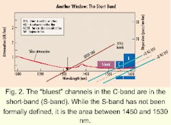
The short-band (S-band) currently exists as the area between 1450 nm and 1530 nm, although it has not yet been formally defined. While erbium-doped fiber amplifiers (EDFAs) provide a cost-effective way to amplify a broad band of channels in the C- and L-bands, there isn't a comparable amplification component for the S-band currently available.
Two promising amplification technologies under development may address S-band issues: Raman amplifiers, which are based on nonlinear Raman-scattering techniques, and thulium-based amplifiers, which are similar to today's conventional EDFAs. Research is currently underway to determine the performance and cost viability of these two emerging technologies.
Once the optimum-amplifier technology is determined, the next step is to develop transmitters to support DWDM in this region.
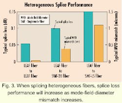
While most wholly owned, long-haul networks contain a single type of fiber in each ring or duct, some smaller operators have been forced to obtain whatever fiber type was available along a certain route. This has resulted in the combination of various fiber types between major population centers. Links that consist of assorted fibers will not cause problems as long as the signals are electrically regenerated at the main junction points. As optical path lengths increase with optical networking, however, heterogeneous splice loss and dispersion management become increasingly important.All other factors being equal, heterogeneous splice performance is highly dependent upon mode-field-diameter mismatch between the two fibers (see Fig. 3). The additional losses due to these heterogeneous splices in all probability will fall well within the overall splice budget.
Dispersion management along a diverse fiber-optic link is accomplished in much the same way as in homogeneous routes. Because chromatic dispersion grows in a linear sense with distance, a "dispersion map" can be generated and dispersion compensation provisioned at either transmit and receive points or in the midstage of a dual in-line EDFA. In the C-band, NDSF fiber gains dispersion at the rate of 17 to 18 psec/km, while NZ-DSF fiber dispersion grows at the rate of about 4 psec/km.
A key goal of dispersion management is to maintain low residual dispersion at each in-line amplifier (ILA) site to ensure that wavelengths can be added and dropped more easily. This management technique requires the use of dispersion-compensation modules (DCMs) at each ILA site, in addition to optical add/drop modules (OADMs). Incorporating both DCMs and OADMs is more expensive and complex on NDSF than on NZ-DSF because of the higher dispersion.
Terrestrial long-haul transmission technology continues to evolve at an astounding rate. The persistant desire to maintain lowest cost-per-bit transmission will lead vendors to continue to introduce products as soon as their solutions are economically viable. At the most basic level, new fiber designs must not radically change cabling processes, bending requirements, or splicing technology. On the other hand, next-generation fiber must minimize the tradeoffs between suppression of nonlinear effects through increased Aeff, dispersion magnitude/slope and emerging technologies such as L-band transmission, higher TDM rates, and S-band operation.
E. Alan Dowdell is a European market development manager at Corning Inc. (Corning, NY).


