Raman amplification key to solving capacity, system-reach demands
Resurrected just last year as a viable commercial technology, Raman can act as a low-noise preamplifier to maintain signal integrity.
Dr. Alan Evans
Corning Inc.
Capacity growth has always been a requirement. The more recent trend is toward flexible, cost-effective connectivity. Distance-independent connections out to 3,000 km are an essential requirement as network traffic becomes dominated by Internet Protocol (IP) over DWDM. End users expect point-and-click Web links to anywhere in the world. Raman amplification can be a key technology to solve both capacity and system reach demands for tomorrow's networks.
Raman amplification occurs when higher-energy (shorter-wavelength) pump photons scatter off the vibrational modes of a material's lattice matrix (optical phonons) and coherently add to lower-energy (longer-wavelength) signal photons. The concept is not new. It was discovered by Sir Chandrasekhara Raman in 1928. Yet, it was not until the 1980s that many believed a practical application had arrived-the distributed amplification of solitons in optical fiber. In the early 1990s, however, that dream all but ended when erbium-doped fiber amplifiers (EDFAs) became the focus instead.
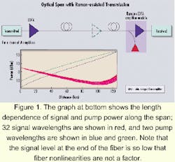
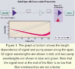
Raman amplification was resurrected as a viable commercial technology in 1999, with several demonstrations of WDM near the zero-dispersion wavelength of dispersion-shifted fibers. In it's new form-so-called distributed Raman-assisted transmission (D-RAT)-the pump light is launched into the fiber at inline amplifier sites opposite to the signal direction. As such, Raman amplification acts as a low-noise preamplifier to maintain signal integrity. Also important, since the signal power is weak near the output end of the fiber, no additional fiber nonlinearities are incurred, which is shown in Figure 1 along with the evolution of signal (red lines) and pump (blue and green lines) through the fiber.For the case of dispersion-shifted fiber, the signal launch power could be greatly reduced to avoid a four-wave-mixing (FWM) penalty while keeping an adequate optical-signal-to-noise-ratio (OSNR) level. Within the last two years, distributed Raman amplification has been extended to number of other applications: a 40-Gbit/sec data rate and 40-wavelength, ultra-long-haul, 10,000-km distance at 1 Tbit/sec; increasing repeater-less DWDM transmission to 450 km; improving spectral efficiency to 0.4 bit/sec-Hz; and hiding the impact of the loss of a wavelength selective switch in 750 km across six nodes.
The benefit of Raman amplification for this wide range of applications can be explained with the help of Figure 1 and the following equation for system-performance quality Q factor. When Q is dominated by signal-spontaneous beat noise from amplified spontaneous emission (ASE):
where P is the signal launch power, F the amplifier noise figure (in linear units), G the amplifier gain (in linear units), N the number of spans (and also amplifiers), Be the electrical bandwidth, and hn a constant. The presence of Raman pumping is equivalent to adding another amplifier in each span of the transmission fiber. The distributed signal gain and associated noise buildup mathematically can be lumped into an equivalent discrete preamplifier just before the inline EDFA. Even without this convenient trick, the improvement in ASE buildup can be qualitatively understood by the fact that twice as many amplifiers in a system require half as much gain in decibel units. Once converted to linear units in the Q equation, even with the 2x increase in the number of amplifiers, there can be >2-dB improvement in Q. That's the reason terrestrial systems at 6x100 km and submarine systems at 140x50 km both work and have similar noise accumulation.
More details on the noise figure of Raman amplifiers can be found in the accompanying sidebar, "Design issues of distributed Raman amplifiers for reduced noise accumulation in long-haul, repeated transmission." Quantitative results require solving coupled differential equations for the forward and backward propagating waves, an example of which is shown in Figure 3 of that sidebar.
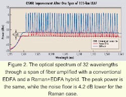
A related quantity to noise figure is OSNR. It is experimentally measured using an optical spectrum analyzer. The spectrum of 32 wavelengths through 125 km of LEAF optical fiber and a conventional EDFA is compared with a Raman+EDFA hybrid in Figure 2. It is clear that the noise floor, and hence the OSNR, of the Raman+EDFA hybrid is more than 4 dB lower than in the conventional EDFA case. From simple scaling, this comparison implies that the system Q is 2 dB greater for the Raman+EDFA hybrid case.
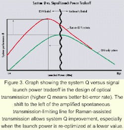
Improvement in accumulated noise is beneficial. However, optical transmission design involves a careful balance between ASE on one hand and fiber nonlinearities on the other. When the power is too low, ASE noise degrades Q; when the power is too high, fiber nonlinearities degrade Q. Figure 3 shows system Q verses signal input power. An added benefit of distributed Raman-assisted transmission is also shown in the Figure 3. The ASE limiting boundary line is shifted to the left resulting in improved Q. It is especially true if the launch power is lowered to a re-optimized value where nonlinearities are decreased.The Q improvement can be used in a variety of ways. Perhaps the most well known is increasing system reach from 600 km up to 3,000 km. The reach extension depends on the amount of Raman gain and what other technologies are being used. Corning has found, both experimentally and through system modeling, that 2.5x increase is possible with 13 dB of Raman gain corresponding to ~400 mW of pump power for LEAF fiber.
But to take full advantage of the reach extension benefit of Raman, two other techniques-slope- and dispersion-compensating fiber and gain ripple management/compensation-are necessary. In addition, forward error correction and span reduction push system reach even further. Reach increase has immediate commercial appeal due to the elimination of expensive electrical 3R regenerators and the drive toward optical transparency over a significant portion of the North American long-haul backbone.
Distributed Raman amplification also provides a critical component for upgrading existing links to 40 Gbits/sec. Without Raman amplification, current fiber types and span lengths of up to 100 km would not be able to support this time-division multiplexing rate cost-effectively. It's likely that span length would have to drop to no greater than 50 km, doubling the number of remote repeater sites.
In addition to its distance advantages, distributed Raman amplification boosts bandwidth capacity in limited-fiber-count networks by enabling tighter channel spacing. Similar to dispersion-shifted fiber, it avoids FWM and allows successful transmission of wavelengths near the zero-dispersion point. From numerical simulations, we have found that a system originally designed for 10 Gbits/sec on 100-GHz wavelength spacing can be upgraded to double the number of channels on 50-GHz spacing without any additional penalty.
Raman amplification is not limited to the three systems described. Enhanced system margin can be applied wherever it is needed-in a single high-loss span, to extend span distances, or to improve noise accumulation with the added loss of wavelength switching and routing elements. Within the inline repeater site, discrete Raman amplification can be applied to broaden the transmission bandwidth beyond that defined by erbium. In the end, Raman amplification provides system designers with several ways to lower the cost per bit of optical networks.
Dr. Alan Evans is a research and development associate at Corning Inc. (Corning, NY). For questions about this article, contact George Wildeman of Corning at [email protected].
Ashiqur Rahman
Corning Inc.
Raman amplification in transmission fibers has been experimented with for more than a decade and deployed in some un-repeatered submarine applications. Now, the availability of high power (>100mW) pump diodes in the 1,4xx-nm wavelength window will make the distributed Raman amplifier a commercial reality for a broad range of telecom applications.
The schematic of a simple distributed Raman amplifier is shown in Figure 1. Two orthogonally polarized pump-diode lasers are polarization-multiplexed and combined with a WDM to provide backward propagating pump power in the transmission fiber. As a result, the forward-propagating signals achieve Raman gain in the fiber. The use of backward pumping reduces the impact of the pump noise in the signals.
The distributed Raman amplifier uses the transmission fiber as its gain medium. Gain performance of the Raman amplifier depends on the transmission fiber properties such as pump absorption, effective area, and the Raman-gain coefficient. These properties of transmission fibers may vary between different fiber types and from the manufacturing distribution within a single fiber type. The Raman gain for a small signal in a long fiber is given by:where gR (in km/mW) is the Raman-gain coefficient, (p (in dB/km) is the pump absorption coefficient, Aeff (in km2) is the effective area, and Pp (in mW) is the pump power. If it is assumed that gR/Aeff = 5.E-04 /(mW-km), (p = 0.25 dB/km, and Pp = 100 mW, then Raman gain is about 3.75 dB.
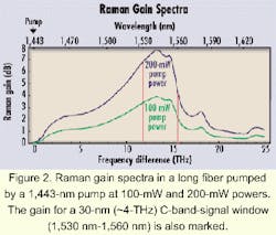
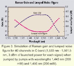
The Raman gain for a particular signal depends on the frequency difference of the pump and the signal. Figure 2 shows the small-signal Raman gain in a long fiber. The gain bandwidth is more than 20 THz with its peak around 13.2 THz. Different signals achieve different amounts of gain, depending on their frequency difference from the pump. Thus, any signal-band window will have some gain ripple. For the 200-mW pumped case in Figure 2, the maximum gain is 7.78 dB and gain ripple (maximum gain - minimum gain) is 3.5 dB, which gives (gain ripple in dB)/(maximum gain in dB) = 0.45 in the selected C-band window.The gain ripple can be reduced by changing the pump wavelength and/or adding more pump wavelengths. Figure 3 shows an example of Raman gain for 40 signals when two pumping wavelengths are used. The maximum gain in this signal band was 14.4 dB with 3.5-dB gain ripple, giving (gain ripple in dB)/(maximum gain in dB) = 0.24. Choosing a different set of optimized pump wavelengths and power can further reduce this ratio. While optimizing the gain ripple, it is important to note that the Raman gain also depends on the pump-to-pump power transfer and, to some extent, on the pump depletion by the signals.
Because of the distributed gain process, the effective noise is less in a distributed Raman amplifier compared with a discrete amplifier. To compare the performance of a distributed amplifier with the discrete amplifier, an equivalent (or lumped) noise factor FR (in linear units) for the distributed Raman amplifier can be defined as:Increasing the Raman gain provides dramatic decrease in the noise figure up to a certain value of Raman gain. Beyond this "cutoff" gain value, the effect of double Rayleigh backscattering increases the noise figure from its minimum, and there is significant impact in system Q value because of signal multiple-path interference.
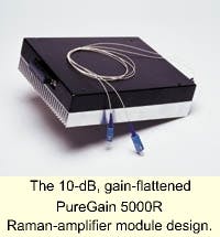
These Corning-developed design tools for modeling and building Raman amplifiers have been applied to realize new Raman-amplifier designs such as the 10-dB, gain-flattened PureGain 5000R Raman-amplifier module (see photo)-the device has been optimized for use in long-reach DWDM systems, span extension applications, and wavelength-increasing applications for dispersion-shifted fiber types.
Ashiqur Rahman is a senior scientist at Corning Inc. (Corning, NY).
