Optical FDM technology benefits ATM metropolitan networks
Optical FDM provides a lower-cost alternative to SONET- and DWDM-based ATM network alternatives.
Scott Wilkinson
Kestrel Solutions
A synchronous Transfer Mode (ATM) metro networks are gaining popularity as an option to circuit-based networks due to their improved bandwidth utilization, flexibility of bandwidth allocation, and ability to handle a variety of voice, video, and data services simultaneously. As these networks are being designed, several dominant network architectures are emerging based on network requirements, and a variety of technology options are emerging for building these networks. Among these options, customer trials indicate that transport systems based on optical frequency-division multiplexing (FDM) are ideally suited for these network applications.
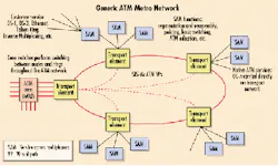
Typically, ATM metro networks are designed with service access multiplexers (SAMs) at the edges and core ATM switches at the center. The SAMs are used to consolidate a variety of customer services into a single ATM stream, which is carried over a transport network to a central switching location (see Figure 1).
Figure 1. Asynchronous Transfer Mode (ATM) metropolitan networks use service-access multiplexers at the network edge to feed traffic to ATM core switches. ATM networks provide more efficient transport of data traffic than circuit-based networks.
ATM offers network providers the ability to more efficiently use the available bandwidth on the transport network. Traditional circuit-based networks are very inefficient for carrying "bursty" data services or bit rates such as 100-Mbit/sec Ethernet that do not conform to the STM-standard payloads. With ATM, bursty services can be statistically multiplexed together so, for example, traffic from 10 100-Mbit/sec Ethernet services can be transported through the network in a data pipe that is 100 Mbits/sec or less. Statistical multiplexing minimizes the amount of "wasted bits," or bits that are not carrying data, which increases the overall efficiency-and revenue potential-of the network.
ATM also offers network providers a variety of quality-of-service (QoS) benefits that cannot be provided by circuit-based networks. Customers can be charged more for guaranteed bandwidth or can opt for lower-cost services with a lower bandwidth guarantee during busy hours. These QoS options allow network providers to offer a wider variety of services at any bandwidth and effectively utilize any and all spare bandwidth on the network.
The ATM devices at the edge of the network (the SAMs) are typically advanced elements that perform a variety of functions such as segmentation and reassembly, policing, and ATM adaptation. These elements have a wide variety of customer-side interfaces such as DS-1 and DS-3, OC-3, Ethernet 10/100Base-T, Token Ring, or Inverse Multiplexing. Many SAMs support native ATM and Internet-protocol (IP) services as well as traditional DS-0-based (voice) services over these interfaces. All of the services are partitioned into ATM cells and put into a single-cell stream, based on the policing (QoS) rules provisioned by the network provider. The high-speed output of a SAM is usually an OC-3c, OC-12c, or (less frequently) OC-48c optical interface.
The OC-Nc cell streams of each edge device must be transported back to a central core location for switching between nodes on the ring and between rings in an ATM network. Depending on the sophistication of the SAMs and the amount of provisioning time invested, some intra-ring switching could be performed using only the edge devices.
However, many network providers have realized that pushing much of the switching all the way to the edge of the network creates provisioning nightmares as the network grows and changes. Similar to the way voice networks are built with centralized switching locations (tandem and toll switches), ATM networks are being built with centralized ATM switching cores. These cores may be composed of a number of interconnected ATM switches in a variety of locations, but they are rarely connected directly to customer end services.
Protection switching in an ATM metro network can be performed at multiple layers, depending on the network-provider preferences. Protection switching can occur at the ATM layer, the transport layer, or both. Switching at the ATM layer alone is often chosen as the best solution, as it avoids any contention between switching mechanisms, but metro networks that combine ATM with some circuit-based traffic usually require a mixture of protection mechanisms.
The transport layer of an ATM metro network is responsible for carrying the STS-Nc cell streams from edge devices back to the centralized switching locations. The transport layer should not interfere with the ATM layer functions, administration, and management. Protection could be provided either by the ATM layer or by the transport layer, depending on the application and the network-provider's strategy. Redundant interfaces (e.g., 1+1) are also often used for connections between ATM switching elements and transport elements to protect against hardware failures, so low-speed redundancy is often required in a transport element. An optimal transport element for this application would, therefore, have to have the following features:
- Transparent transport of all incoming signals.
- Flexible crossconnects.
- Per-channel optional ring protection.
- Optional low-speed protection.
Transparent transport of all signals implies that the header bytes in the SONET framing of the ATM signals are not modified by the transport layer. Although many vendors like to talk about putting ATM directly onto fiber and avoiding the SONET layer, ATM optical outputs are still SONET framed, and many use the SONET overhead bytes for signaling and communications. These communications protocols are not always SONET standard, so terminating and regenerating the overhead bytes can destroy any benefits that may have been inherent in the signaling.
The ability to flexibly crossconnect traffic is necessary in a network expected to grow and change over time. As new demands are created or moved to other locations, it should not be necessary to re-engineer the entire network. Crossconnects allow traffic to be routed around the network, as required through simple software commands, without the need to rearrange hardware-an expensive and time-consuming alternative.
The cost of a crossconnect fabric is directly related to its granularity, so it is important not to over-engineer the crossconnect in a network element. For example, higher-capacity SONET elements (OC-48 or OC-192) typically do not include VT1.5-level crossconnect fabrics as a standard feature due to the added cost and the fact that most high-speed traffic can be routed at the STS-1 level or higher without compromising network efficiency. For an ATM metro network, the smallest "pipe" that would be routed through a crossconnect fabric is STS-3c. Therefore, a simpler crossconnect fabric that operates at the STS-3c/STS-12c level could be designed to minimize the cost of the transport layer in an ATM metro network.
There may be some benefit to having a limited ATM fabric in a transport element to more fully utilize the bandwidth pipes. But in many applications, the added complexity and expense obviate any efficiency benefits-especially if the SAMs are already doing a good job of filling the OC-3c and OC-12c pipes.
Network providers are divided on the issue of where to place protection in an ATM metro network-at the ATM layer or the transport layer. Multiple restoration methods at each layer can cause switch contention or "ringing," which can create multiple switch events for a single failure. Therefore, network providers often turn off either the ATM-layer or the transport-layer protection when possible.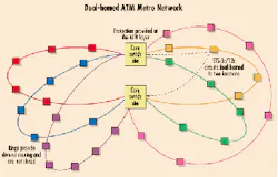
Figure 2. The dual-homed Asynchronous Transfer Mode (ATM) network has a pair of central core switching locations. Rings link other ATM resources to these core switches. The architecture minimizes the necessity for expensive crossconnect fabrics.
For a transport layer that is flexible enough to carry some transport-layer protected circuit-based traffic along with the ATM traffic, the issue becomes even more complicated. The ability to flexibly enable or disable transport-layer protection on a per-channel basis is key to a transport-layer network element in an ATM metro network.
Low-speed protection, likewise, is a debatable feature for an ATM metro network. Some network providers prefer to let the ATM layer handle all restoration and treat the transport layer as "virtual fiber." In those networks, the transport layer provides path diversity and signal consolidation. The benefit of this strategy is more efficient utilization of network bandwidth, since low-priority traffic can be placed on the interfaces that would have been reserved for protection.
Other network providers prefer to isolate failures outside of the transport network so they are not seen by any other elements. This strategy relies on redundant interfaces between the transport elements and the ATM elements (SAM, core switch, etc.). The benefit of this strategy is that local failures (hardware failures, jumper failures, etc.) do not affect the rest of the network.
Further complicating the issue, a transport layer that carries circuit-based traffic in addition to ATM traffic may require redundancy on some low-speed interfaces but not on others. The optimal transport-network element for ATM metro networks should offer the option to protect or not protect low-speed interfaces as required.
Transport systems based on optical FDM technology are uniquely equipped for use in an ATM metro network. Optical FDM combines FDM, digital signal processing, and optical modulation techniques. Much as in the subcarrier multiplexing common to hybrid fiber/coax applications, optical FDM begins with an information stream modulated independently onto a subcarrier at an assigned frequency. Multiple subcarriers-each potentially carrying a different ATM stream-are combined electronically; the resultant composite signal is used to modulate the light from a single laser transmitter. At the receive end, a single photodetector converts the optical signal back into an electrical signal. A sequence of frequency conversions and electronic filters separates the subcarriers into constituent signals.
The spectral efficiency of optical FDM provides high-speed transmission-as much as 10 Gbits/sec on a single wavelength. Recently, an optical FDM transmission system has been designed as an interoffice and access transport platform for carrying optical signals efficiently over metropolitan distances. The low-speed SONET interfaces of the system are protocol-independent, which means that any OC-Nc signal can be carried transparently, with the SONET overhead bytes passed intact. The crossconnect fabric of the system is designed to manage signals at the STS-3 level or higher, adding network flexibility while reducing the expense that a more complex crossconnect would require. High-speed and low-speed protection can be enabled or disabled on each channel independently, depending on the network requirements. In addition, the optical FDM system offers features that enhance the manageability and reliability of an ATM metro network, including:
- Full SONET performance monitoring (PM) on all incoming signals gives the network provider a continuous view of the network conditions.
- High-speed per-channel PM provides a view to the health of all signals, both SONET-framed and nonframed.
- Variable-rate interfaces allow other nonframed traffic (e.g., legacy async, Escon, Fibre Channel, D1 video, etc.) to be carried on the same transport network.
- Full regeneration of all pass-through signals reduces network-engineering complexity and makes network changes much simpler to implement.
Analysis of a variety of customers' ATM metropolitan networks has shown the applicability of optical FDM technology to metro applications. The networks analyzed fall into two broad categories: dual-homed architectures and core ring architectures.
The dual-homed architecture (see Figure 2) is characterized by two central core switching locations. All other sites are linked to both core switching sites by "rings" that are not completely closed. The advantage of a dual-homed architecture is that all switching is performed in a centralized location that is logically duplicated at a redundant site for protection. Keeping all of the switching at a centralized location reduces the cost of the network by limiting the number of expensive crossconnect fabrics required and improves the manageability of the network by allowing most provisioning and administration to occur in one central location.
The traffic-bearing rings in the dual-homed architecture are not physically closed, so protection is provided entirely by the ATM layer. The transport layer provides signal transparency, route diversity, and signal consolidation. To build this architecture, the optical FDM system is deployed in linear chains starting in one core location and ending in the other core location, with a total capacity of 10 Gbits/sec (64 OC-3s) routed from the field to each core location. Since the optical FDM system can operate each of its high-speed shelves independently of each other, the systems at the core locations are able to participate in two linear chains, reducing the amount of equipment required at the central locations.
For the largest customer study performed of this type, there were a total of five rings with demands scaling from a total of 280 OC-3c signals to 344 OC-3c signals over a five-year plan. The network was analyzed with an optical FDM solution, an OC-192 solution, and a dense wavelength-division multiplexing (DWDM) solution. In each case, the traffic was free to be aggregated up to OC-48c if necessary to save costs.
The ability of the optical FDM system to scale from a few OC-3s to a full 10-Gbit/sec capacity on both the high- and low-speed sides gave it a clear advantage for first cost. Also, the low component cost and the low cost of pass-through channels gave optical FDM a long-term price advantage. In the final analysis, the optical FDM solution was more than 45% less expensive that OC-192 solutions over the five-year period and more than 70% less expensive than DWDM solutions over the same time frame.
The core-ring architecture is used primarily for very large networks covering a wide area and using multiple core switching elements. In the core-ring architecture (see Figure 3), "petal" rings are homed back to a central core ring. On the petal rings, lower-capacity pipes (e.g., OC-3c) carry user traffic from attached SAMs or other ATM devices back to ATM core switches located between the petal rings and the core ring. The core ring is used to transport inter-ring traffic between core switching sites using larger pipes (e.g., OC-12c). In this architecture, all rings are physically closed, so high-speed protection-such as unidirectional path-switched ring (UPSR) or bidirectional line-switched ring (BLSR)-can be employed, if desired.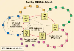
Figure 3. The core-ring architecture features "petal" rings that link service access multiplexers or other Asynchronous Transfer Mode (ATM) devices to the core switches. Protection is provided at the ATM layer.
The advantage of a core-ring architecture for very large networks is that the core switching is spread out to multiple sites to limit the processor power required at any one location. But by keeping all of the switching on the core ring, some of the benefits of a centralized architecture (e.g., centralized management and reduction in the number of switch fabrics) can be realized on a broader scale.
In the core-ring architecture, the optical FDM system is deployed in rings, with per-path UPSR protection enabled, if necessary. On the petal rings, up to 64 STS-3c signals can be carried back to the central-switch sites. On the core ring, up to 16 protected STS-12c signals can be carried if UPSR protected (more if not protected).
The advantages of the scalability of the optical FDM system from a few OC-3s to 10 Gbits/sec are more easily seen in such large networks, where some petal rings may be very lightly filled (unlike the dual-homed architecture where rings are typically very well packed).
In the largest study performed on a core-ring ATM metropolitan network, the core ring consisted of seven switching sites connected by a total of 14 STS-12c circuits. The nine petal rings consisted of over 90 locations connected by 20 to 50 STS-3c signals per ring. In this study, all interfaces were analyzed as 1+1 protected and all rings were UPSR protected. Many of the petal rings were very lightly loaded, which gave the optical FDM system an advantage over the other technologies analyzed because of the low first cost of optical FDM common equipment. The central core ring was nearly filled, which gave this architecture similar advantages as the dual-homed architecture. In the final analysis, the optical FDM architecture was confirmed by the customer to be 30% to 50% less expensive that SONET solutions and significantly less expensive than DWDM solutions, which were considered too expensive to deploy.
An additional study that accounted for the coincident voice traffic (DS-3 circuit-based traffic) was also provided. Because optical FDM is protocol-independent, this voice traffic could be combined with the ATM traffic on the same infrastructure-either through the existing legacy asynchronous multiplexers or on SONET multiplexers connected to the optical FDM system. In this analysis, the cost of adding existing and predicted voice traffic on top of the ATM network was only about 30%, even in areas where the voice-traffic demands were nearly equal to the ATM demands.
Network providers are deploying ATM metropolitan networks to gain the increased bandwidth efficiency and service flexibility that ATM provides. Optical FDM is the optimal transport-layer solution for ATM metro networks. The combination of features offered by optical FDM is uniquely suited to transporting OC-3c, OC-12c, or even OC-48c signals from the service locations to the central switching locations.
In economic studies performed in coordination with customers, optical FDM has been a clear cost winner in a variety of situations. In particular, an optical FDM network was 30% to 50% less expensive than SONET architectures and up to 70% less expensive than DWDM architectures (using forward pricing for SONET and DWDM). Also, the modularity of available optical FDM equipment means that ATM metro networks based on this technology have the lowest first cost of all options, allowing network providers to recover costs quickly in the increasingly competitive metropolitan market.
Scott Wilkinson is senior manager of applications engineering at Kestrel Solutions (Mountain View, CA) He can be reached at [email protected]