Are the components you use strong enough for the high-power systems you need?
JOSEPH KULAKOFSKY, E-TEK Dynamics
When you consider 1 W of power, it doesn't seem like much. After all, the nightlight in your bathroom is five times brighter. However, in fiber optics, this energy may be crammed into an area only 8 microns in diameter. The resulting photon flux over the small cross section of the fiber, equivalent to about 1.9 million W/cm2, is about 300 times greater than the photon flux (6,200 W/cm2) at the surface of the sun! So why doesn't everything melt? Very few of these photons are actually absorbed at any point in the singlemode fiber because of its high purity. But how will other components perform at these higher powers?
To achieve greater performance and economies, systems are being designed with longer spans and more wavelength-division multiplexing (WDM) channels. Higher powers enable design strategies that deliver increased bandwidth and functionality, and in some cases, reduced costs.
For example, long-haul systems can save money by increasing the distance between repeaters. What used to be a 40- to 50-km link now spans 80 to 100 km between amplified repeaters. However, the longer distances require increased power output from the booster and inline amplifiers. The high power of 1,480-nm sources now allows system designers to benefit from the use of Raman amplifiers. In fact, Raman amplifiers must operate at power levels above 500 mW where nonlinear effects are present in the fiber. If multiple pumps are used, they will need to be multiplexed in some fashion and then multiplexed with the signal path, which results in more components in the high-power path.Remote pumping of erbium-doped fiber amplifiers (EDFAs) is another application for high power. Separating the laser and the erbium-doped fiber (the point of amplification) is advantageous, for example, so that the laser can be located in a more accessible or safer location. Increasing the distance between the pump and the erbium-doped fiber requires higher power, however. Advances in laser technology have pushed 1,480-nm-region pump power over 500 mW to 1 W and above into the fiber. This power can be multiplexed onto the signal fiber and sent far down the path to strategically placed pieces of erbium-doped fiber. The erbium-doped fiber lases upon receiving the 1,480-nm booster signal, and the result remotely boosts the level of the signal power.
One of the more compelling benefits of high power is the ability for higher-channel-count dense WDM (DWDM) systems. Increasing the number of DWDM signals is a cost-effective way to boost the bandwidth of a system. An EDFA must work a lot harder, however, to provide the same amount of per-channel amplification in, for example, a 40-channel system versus an 8-channel system. Boosting eight channels each at 0.5 mW (total power ~ +6 dBm) by about 25 times requires a total output from the EDFA of 100 mW, or +20 dBm. To give the same amount of boost to each channel in a 40-channel system would require a 500-mW (or +27-dBm) amplifier.
It is clear that the fiber can reliably carry the signal at such high powers. But as the signal moves out of the fiber core and into the optical components, there may be potential for failure. The photon intensity in 1-W systems is enough to destroy optical materials, surfaces, and coatings.
Traditionally, the concern for such systems revolved around the reliability of the pump and source lasers employed. But having 1 W or more in the fiber creates new challenges for the passive optical components that direct these signals in amplifiers and other modules. Little work has been done to test, specify, and set standards to ensure that the various components will perform satisfactorily in these new high-power amplifiers.
The highest powers are generally evident in the pump paths and signal paths after amplification. In the pump path, multiple sources may be combined using different wavelengths or polarization. Then the combined pump signal is multiplexed with the 1,550-nm signal. After amplification, all the single-path components such as taps and isolators experience the high power converted from the pump signal. Optical components for high power may include taps, isolators, wideband and narrowband WDMs, and polarization-combining modules.
The collimating process used in a typical bulk-optic component becomes a concern under high power. Collimating the light has the desirable effect of creating an expanded parallel beam that is easier to manipulate. After traveling through various components such as a thin-film filter or an isolator core, the beam reverses itself through another collimator and is launched back onto the fiber. But as the light is focused on and off the fiber tip, the optical intensity is at its greatest, with the greatest potential for damage.The larger collimated beam itself at 500 microns in diameter (compared to 8 microns in the fiber) results in much less intensity-1/4,000th of that in the field in the fiber core. The large beam still poses problems for the optical components, though. Any dirt or other contamination on the surfaces can act as a tiny lens. The dirt locally focuses the beam until the intensity burns a hole in the surface. Increased insertion loss is the result. This mode of failure usually shows up early in the life of the component. Therefore, it may be possible to devise a quality-assurance test to screen components after manufacture.
Components assembled with epoxy have an additional failure mode. Epoxies are made of long chains of organic polymers. Several years ago, epoxies under prolonged exposure to high optical intensity would yellow or darken. As the epoxy became darker and more opaque, the insertion loss rose. Today, epoxies are more resistant to this type of breakdown. However, at higher optical powers, how will the epoxies react? Also, since this is a longer-term failure mode, it may be difficult to devise quality tests on the production line for products containing epoxy in the optical path.
As stated previously, the test, specification, and setting of standards to ensure that high-power components will perform as required represent new areas of research. Thus, companies such as E-TEK that are working in the field currently must establish their own practices and test methodologies. As an example of how one might test components for high-power applications, let's consider work performed on E-TEK's thin-film interference filter-based 1,480-/1,550-nm WDM.Long before testing began, we considered design elements that would allow the component to survive under high-power conditions. Thus, for example, the optical paths of this WDM are free of epoxy. The optical surfaces are separated by air, and every surface has an AR coating designed specifically for an air interface. All coatings are made of layers of "hard" material such as TiO2 to resist flaking and delamination.
Next, we addressed manufacturing issues, specifically those of contamination. The de vices were as sembled in a clean-room environment. Although the room itself is Class 10,000, actual component construction takes place under lam inat ed flow hoods where the particulate matter is on the order of Class 100 (i.e., lower levels of particulates), minimizing the chance of any foreign particles impinging on the optical surfaces.
Finally, we developed a quality-assurance test for high power. Since dirt and other foreign material do not migrate easily into a well-sealed optical component, contamination is most likely during manufacture and less likely after installation (barring physical damage to the component). Thus, a test under high power should cause any beam focusing to occur quickly, and damage could be easily assessed in a relatively short time period.
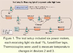
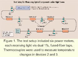
Figure 1 illustrates the testing setup. We obtained a high-power source at 1,480 nm from SDL Inc. Although rated for over 2 W, we did not want to stress the laser during the test, and so the output power used was approximately 1.6 W. Five thin-film interference filter-based 1,480-/ 1,550-nm WDM devices were prepared.
To replicate a worst-case test, the 1,480-nm signal was in transit through the filter, and the 1,550-nm signal would act in reflection. Operating in transmission subjects both collimators in the package to high power. The 1,550-nm legs were not used. Five devices were fused in serial fashion. Dual 1% fused-fiber taps were placed before and after each device (for a total of six taps), with each directing some power to a power meter.
Six power meters enabled continuous monitoring during the test at all the points on the chain. The dual 1% taps were required to avoid damage to the power-meter heads. A beam dump collected all the remaining power at the end of the chain. In addition, we monitored any temperature changes in the devices that the high-power conditions might cause. We attached thermocouples to device #2 and device #3 in the chain. Device #2 was on a metal plate (a good conductor of heat), and device #3 was on a piece of cardboard (a poor conductor of heat).
We first subjected each device to a high-power soak of 2 W for 80 min. Next, we tested the devices at 1.1-1.5 W for 500 hours. We monitored temperatures and losses.
Table 1 contains the results for the high-power soak. No significant change occurred in the insertion loss for either the 1,480- or 1,550-nm path.
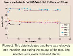
After the soak, we assembled the devices together (see Figure 1). Based on the laser output and the insertion losses of the taps and WDMs, we calculated the input power to each device, which ranged from 1.1 W to 1.58 W. The test ran for 500 hours. Figure 2 is a graph of the results.
The data shows that after a small initial change, no additional significant changes in insertion loss (IL) occurred for any of the devices. The initial change was due to a small temperature-dependent loss for the WDMs. Four of the five devices had less than a 0.05-dB change. For long-term accuracy, the stability of the laser source was about ±0.02 dB. Any long-term changes in the WDMs were less than the measurement accuracy of the test.It is unlikely that any changes in insertion loss could be attributed to the 1% taps used in the test. The taps used were wideband biconical taper fused-fiber taps, which can handle high power because the optical field never leaves the core of the fiber. In the fusion region, the optical field is actually spread out wider than normal, further lowering the power density. Since the singlemode fiber core is unaffected by the high power, the fused region of the two cores should be similarly unaffected. Each tap was measured after the test. There were no changes in insertion loss larger than the accuracy of the test set.
We monitored two devices for temperature changes during the test. Through absorptive or dispersive effects, devices under high power may lose a tremendous amount of photons. If these effects render themselves as a heat rise in the device, unwanted temperature-dependent losses may result. Such losses could impede system performance and pose a long-term reliability issue.
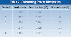
Knowing the input power and insertion loss, calculating the power dissipated inside each device yielded the results displayed in Table 2.
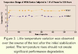
The two devices (#2, #3) measured for temperature dissipated 94 and 96 mW, respectively. For a given power input, the insertion loss is related to the dissipation of each device. The losses for the devices in this test were low, minimizing any temperature effects.The system was calibrated for temperature as follows: With the high-power laser operating inside the cabinet, but not connected to the devices, the temperature was allowed to stabilize at each device for 24 hours. Readings were 29.1°C and 30.1°C, respectively, for the two devices. Figure 3 shows the temperature variation over the 500-hour test. After an initial stabilization period, the dissipation of 95 mW resulted in a slightly higher temperature for the devices. The temperature of the device on the metal surface rose 2.9°C above the ambient. The temperature of the device on the cardboard surface rose only 4.4°C. That is a relatively minor temperature rise and would have no immediate impact on insertion loss and no long-term reliability issues.
The WDM devices tested performed well under high power. They exhibited low insertion loss, minimal temperature rise, and no indication of long-term reliability issues. Key design and manufacture elements included avoiding epoxy in the optical path, using high-quality AR coatings, and assembling under clean conditions. As a result, the devices exhibited no change in performance after being subjected to an 80-min soak at 2 W and after 500 hours of optical power in excess of 1 W.
However, further tests will need to be completed on various optical components to build up a working database of information. For example, isolators, which are designed for high loss in the reverse direction, are likely to experience relatively high heat and temperature gains if they are subjected to high levels of reverse power. Testing may indicate the need for redesign or the use of a heat-sink to dissipate the heat or to ensure satisfactory performance at higher temperatures.
The implication for system designers and component manufacturers is the need to address these and other high-power considerations in the design, specification, manufacture, testing, and selection of components as systems approach and exceed 1 W. Today's long-haul and high-channel-count WDM systems demand increasing optical power. High-power testing of system elements will be an important underpinning of the confidence that these systems can deliver the required performance and long-term reliability.
Joseph Kulakofsky is senior manager, technical services for E-TEK Dynamics (San Jose, CA).
