Optical fuse protects optical systems from excessive power
Almost every electrical system contains an over-current switch, namely, a fuse. Although the fuse has no functional role in the system, it is considered an essential part. However, optical systems lack such a device and therefore are unprotected from excessive input power. Unfortunately, with optically amplified systems becoming more common in the lab and field, many of us have experienced damage to optical equipment or components due to over-power events.
This problem promises to grow since the power applied in optical fibers has increased significantly in recent years. The trend includes DWDM telecommunications systems with a large number of channels, high-power lasers and amplifiers, and applications in the medical- or industrial-laser fields.
Some existing high-power systems include sophisticated protection schemes, mainly based on software-controlled feedback loops. Here, we present an alternative: the optical fuse, a totally passive component designed to protect against excessive power transmission. The optical fuse is immediately switched off as a result of an over-power event.
The optical fuse has a single input and single output port. When the input power is lower than a certain threshold level, the fuse is transparent. But when the power exceeds the threshold level, the fuse becomes permanently opaque.Experimental results are shown in Figure 1. Here, the output power increases with the input power up to the threshold power, after which the output power decreases dramatically. In the specific example, the threshold power is about 30 dBm (1 W). However, the threshold power is currently selectable from 25 to 32 dBm (300 mW to 1.5 W), and fuses with lower threshold powers are now under development. Also, the output power dropped by approximately 25 dB at the threshold, reducing the output power to about 0.3% of its original power at the time the threshold power was exceeded (typical drop values are between 10 and 20 dB—a 90–99% drop in the input power).
To protect against over-power, the optical fuse can be placed either at the input of a sensitive optical device such as a detector or at the output of a high-power device such as a laser or an optical amplifier. It can be integrated within an optical device (e.g., between different stages of an optical amplifier) as well. The normal operation power of the system should be up to 3 dB (50%) below the threshold power. Under these operating conditions, the insertion loss of the fuse is between 0.5 and 1 dB (80–90% transmission), and it has low polarization loss and high return loss (low reflectance).
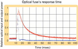
The lack of simple protection devices has encouraged the development and use of sophisticated methods, including software-controlled feedback loops, to prevent over-power. These methods need fast response time, generally using expensive fast detectors, switches, or attenuators, to ensure damage prevention from power spikes or short pulses that may occur in high-power erbium-doped fiber amplifiers or Raman amplifiers.The optical fuse is fast (see Figure 2). Here, the input is a high-power pulse (marked in red). As shown, the output pulse (blue) is blocked after the input pulse exceeds the threshold power. Here, the response time is shorter than 5 µsec. Even shorter response times were measured for more powerful input pulses.
Like other passive components, the optical fuse is transparent to modulated and unmodulated signals. It is currently available in a fiber-pigtailed design and operates in the C- and L-bands, using standard singlemode fibers. However, the fuse is broadband and can operate in other spectral regions such as 980, 1060, or 1300 nm, using other fibers. Also, the fuse can be connected using either a replaceable patch-cord style or fusion-splice-compatible configuration.
Introducing optical fuses into test setups in the laboratory or into networks can help ensure that over-power events will result in damage to the optical fuse itself and not to other components or subsystems. An activated (burned) fuse blocks the forward power without increasing the reflected power and does not induce damage to its surroundings. In addition to preventing costly equipment replacement, the system downtime can be minimal, with no time spent pinpointing damaged equipment.
The optical fuse could become as commonplace in optical systems as electrical fuses are today in electronic systems. The fuse market will encompass devices in telecom systems, testing equipment, medical optics, and defense optical systems. As a standard component of more expensive devices, the optical fuse will save repair costs for the manufacturer and replacement costs for equipment operators.
The fuse can and should be included in less expensive devices, since the ease of use and labor savings are significant advantages over the complexity of replacing, reinstalling, and reconnecting a series of simple devices embedded in a large system. Optical testing and measuring equipment should be an early adopter of the fuse. This broad category of devices, used by almost every optical laboratory, includes expensive equipment that is often particularly sensitive to spikes or high power.
Medium- and high-capacity trans-ponders and transceivers in fiber networks should prove to be leading "host" devices for the fuse. Basic network components such as power-sensitive optical PIN and avalanche photodiode receivers and photodiodes that generate electrical signals according to light characteristics will also be included in the initial fuse markets. Erbium gain blocks, another class of gain-increasing amplifier for DWDM systems, will also be candidates for the fuse. Lastly, medical equipment and instrumentation may also become an important and early market for the optical fuse.
The optical fuse is a passive, customer- or field-technician-replaceable component that provides protection from the failure of major subsystems and components due to exposure to over-power. Although this concept has been used for many years in the electric and electronic fields, the introduction of the optical fuse allows for new protection schemes in optical test equipment and networks.
Tom Marrapode is director of marketing, Fiber Optics Division, Molex (Lisle, IL). Dr. Ram Oron is chief technology officer at KiloLambda Technologies (Tel Aviv).


