Chromatic dispersion compensation improves extended-reach architectures
Increasing the reach between telecommunication nodes is a very attractive business proposition in many types of telecommunications networks. This article explains how fiber Bragg grating (FBG)-based dispersion compensation offers an enabling technology for implementing an extended-reach architecture in long-haul, metro, and submarine networks.
The incumbent technology used for compensating chromatic dispersion in high-speed networks is dispersion compensation fiber (DCF). DCF features dispersion over the transmitted bandwidth that is in the opposite direction of the transport fiber. The trick is to put enough DCF in line with the transmission fiber to counterbalance the dispersion the transmission fiber induces. The greater the length of the transmission fiber, the greater the needed compensation will be, hence the longer the DCF length will be. So the bottom line is that a high level of compensation creates high insertion loss, high cost, and bulky dispersion compensation modules (DCMs).
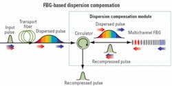
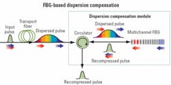
The approach with FBG-based compensators is somewhat different. Figure 1 shows how it works: The pulse that gets dispersed by the transport fiber is recompressed using a multichannel FBG reflector. The specific level of compensation is related to the FBG written pattern. The result is that the size, insertion loss, and cost of the DCM are no longer tightly coupled to the level of compensation needed.FBG technology for chromatic dispersion compensation offers several benefits. For long-distance compensation, the insertion loss is much better than DCF-based approaches. The FBG-based DCM occupies a much smaller footprint. Without introducing nonlinear effects, a FBG-based DCM can tolerate power levels that are much higher than the highest power levels we can find in a network. In the case of a DCF-based DCM, nonlinear effects start to appear at a fairly low level of optical power, which limit their use to places where the signal level is relatively low (generally after a preamplifier or in the mid-stage of in-line amplifiers). The cost of DCF-based compensation is directly proportional to the amount of fiber necessary. In the case of FBG-based compensation, cost is more a function of the number of FBGs used.
Extending the reach in unrepeatered submarine networks makes a lot of business sense. Eliminating the need to install active undersea equipment provides substantial cost savings, and increasing the reach directly expands the addressable market by opening new opportunities where repeatered systems are too expensive to be used.
To address the different reach requirements, there are many possible configurations and technologies in play. In terms of transmission fiber, the ubiquitous choice is pure silica-core fiber because of its low loss and high optical power handling capability. For the amplifier, depending on the reach, many types of amplifier blocks can be used, such as erbium-doped fiber amplifiers (EDFAs), lumped remote amplifiers, remotely optical pumped amplifiers, or distributed Raman amplifiers.
On the chromatic dispersion compensation side, no matter which configuration is used, FBG-based DCMs represent the best cost versus benefit solution.
Any reduction in insertion loss directly translates into a reduction of the required overall gain the multiple amplifiers within the system must provide. As a practical example, compensating for 320 km with DCF-based DCMs creates an insertion loss of more than 20 dB, compared to only 5 dB for a FBG-based DCM. The difference (>15 dB) means that one less amplifier is needed to cover the same 320-km reach, resulting in a substantial cost savings.
The use of FBGs reduces costs in two ways. First, the insertion loss is low enough to enable concentration of all the compensation at a single location (which is not recommended for DCF-based DCM because of the high insertion loss it would induce). Compensating via one module instead of two decreases the overall dispersion compensation cost by around 20%. Second, for a similar compensation distance, the upfront cost for FBG-based DCM is at least 25% lower than DCF-based DCM.The tolerance of FBGs to high optical power enables installation of the DCM wherever it is the most advantageous within the specific system architecture. It can be installed before the booster amplifier of the transmitter side, at the output of the booster amplifier (in some cases, providing a slight improvement on the system OSNR), or after the receiver side preamplifier (which could be advantageous for the overall system OSNR).
FBG-based DCMs are compact enough to fit on a system line card-even modules compensating up to 400 km. Compensation for a similar distance with DCF-based DCMs would require four modules that would take two precious rack-mounting spaces.
The usual way to manage dispersion in repeatered long-haul submarine systems is to use cables that mix transmission fiber having positive dispersion (D+ fiber) with fiber having negative dispersion (D- fiber). Both types of fibers are alternatively used in each span between the in-line amplifiers to reduce the overall dispersion level close to zero.
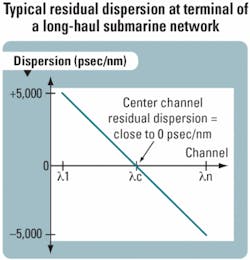
This configuration is quite good except for one issue: the fact that the dispersion profile over the transmission bandwidth of the D+ fiber never exactly matches (in the opposite direction) the profile of the D- fiber. This mismatch brings residual dispersion close to 0 psec/nm for the center channel but to a maximum for the channels located at both ends of the transmitted spectrum. This residual dispersion accumulates throughout the link; the longer the link, the higher the residual dispersion becomes that must be compensated at the terminal ends.
Figures 3 and 4 provide a typical example of a long-haul submarine network where the accumulated residual dispersion is -5,000 psec/nm on the first channel and +5,000 psec/nm on the last channel, while the center channel is close to 0 psec/nm. The residual dispersion slope to be compensated at the terminal depends on the matching between the D+ fiber and D- fiber and on the total length of the network. This slope variability makes it difficult to compensate the residual dispersion all at once for all the channels; this is why compensation must be done on a per-channel (or a group of channels) basis as shown in Fig. 3.FBG-based DCMs are particularly well adapted to compensate this residual dispersion.
When DCF-based DCMs are used, the large variation in the amount of compensation required to be applied to the end channels compared to the center channels creates a problem: End channels need to be amplified, while the center channels don’t. To cope with this problem, band multiplexing and demultiplexing must be used to create small groups of adjacent channels to which the right level of amplification (and a first level of dispersion compensation) is applied. These bands are then multiplexed (or demultiplexed) together to get in (or out) of the transmission fiber. The insertion loss of FBG-based DCMs being either 3 dB (for modules compensating for 3,400 psec/nm or less) or 5 dB (modules compensating between 3,400 and 6,800 psec/nm), this closeness has the effect of eliminating the need to multiplex/demultiplex and amplify on a band basis. The result is a much simpler configuration and substantial capex savings.
Compensation on a per-channel basis on the receiver side (post-compensation) and on the transmitter side (precompensation) means that a lot of DCMs are required (at least one per channel on each side). As a general rule of thumb, FBG-based DCM space requirements at each terminal represent less than 25% of what is needed for DCF-based DCMs.
The 25% cost difference in favor of FBG-based DCMs directly translates into further capex savings.
Another option would be to use “colorless” tunable FBG-based DCMs (TDCMs). The result would be that the same device can be used on each channel (instead of a different DCM for each channel). Use of TDCMs would greatly simplify network engineering and substantially reduce the spare parts inventory.
When fiber optics started to be used in telecom transport networks during the 1980s, the average distance between nodes was in the range of 30 to 40 km. The advent of EDFAs during the 1990s was the enabling technology that allowed an increase of the average distance between nodes by a factor of two. Nowadays, Raman-based amplifiers offer the same opportunity to extend the reach between nodes by a factor of two.
Based on analysis performed by carriers (such as Verizon), extending reach by a factor of two (from 80 to 160 km) using hybrid Raman/EDFA amplifiers (distributed Raman preamplifier combined with an EDFA booster) provides several benefits.
Capex is reduced roughly 30% from cutting by 50% the amount of support equipment needed (e.g., optical supervisory channels) in the skipped huts and using one DCF module to compensate the chromatic dispersion for 160 km at once (instead of using two DCF modules compensating 80 km each).
Opex is reduced with 50% fewer sites to prepare, provision, install, and maintain equipment; decreased sparing costs; and reduced network footprint.
Network availability is increased as a result of fewer network elements.
Using FBG-based DCMs would enhance further the attractiveness of this extended-reach scenario by bringing three additional benefits.
The difference in insertion loss between the DCF-based DCM (~13 dB) and the FBG-based DCM (3 dB) to compensate for 160 km is about 10 dB. This can directly translate at the hybrid Raman/EDFA line amplifier level into 10 dB less required gain. On top of that, the FBG-based DCM could be placed at the output of the amplifier, thus eliminating the need for mid-stage access and hence providing more potential capex savings.Reducing gain at each node by 10 dB means that one amplifier stage can be eliminated from the booster. This will bemefit the amplifier noise figure and improve the OSNR.
Most metro networks are engineered to work with 2.5-Gbit/sec (or lower) transmission speed. When it is time to add 10-Gbit/sec channels to metro networks engineered to 2.5-Gbit/sec design rules, dispersion is a major issue.
The first solution to this dispersion issue is to add static dispersion compensation to each span of the network. However, this increases the loss throughout the network, which must be compensated by increasing the gain, in most cases at every amplification node in the network. Such an upgrade ends up being very expensive.
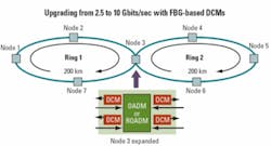
To help keep the upgrade cost as low as possible, some transponder and transceiver manufacturers have developed extended-reach, dispersion-tolerant 10-Gbit/sec products that can be used directly in networks designed for 2.5 Gbits/sec. To achieve their high chromatic dispersion tolerance (representing links up to 200 km), these transponders use special modulation formats and/or optical pulse shaping and/or digital signal processing. Even with these special transponders, however, network spans of more than 200 km of optical reach will require the retrofit of DCMs to the network. FBG-based DCMs are particularly well adapted for use with these extended-reach, dispersion-tolerant 10-Gbit/sec transponders.Since the insertion loss of FBG-based DCMs isn’t coupled with the amount of compensation required, it becomes feasible and advantageous to concentrate the DCMs at a few locations in the network. Figure 5 provides a simplistic example where the DCMs are added at the point of convergence of two 200-km rings of a metro network. In this example, 10-Gbit/sec dispersion tolerant channels can be added from any point toward any other point.
Fewer compensation points means less added loss to the network, which leads to fewer amplifiers to upgrade. In addition, the high tolerance to nonlinear effects of FBG-based DCMs makes them installable at the output of booster amplifiers. This capability means that it is even possible to only change the booster stage of the amplifier where the DCMs are added, leaving all the in-line amplifiers of the network unchanged. The result is much lower overall capex.
The small footprint of FBG-based DCMs makes them easier to retrofit, especially in small huts or in collocation applications where space is very constrained.
FBG-based chromatic dispersion compensation is a low-cost, low-insertion-loss, and high-performance technology that brings unequaled benefits when it is time to increase the reach of telecom networks. The present installed base of such DCMs-many thousands of units deployed in the past four years-provides strong evidence to support this conclusion.
Daniel Mailloux is senior marketing manager, Martin Guy is vice president of technology and product line management, and Carl Paquet is product line manager, at TeraXion (www.teraxion.com); e-mail: [email protected].


