Todays optical amplifiers enable tomorrows optical layer
Today`s optical amplifiers enable tomorrow`s optical layer
There are two major types of erbium-doped fiber amplifiers. Each has advantages and limitations, which should be considered in light of the anticipated application.
thomas fuerst
alcatel telecom
Much has been written about the two main applications of the erbium-doped fiber amplifier (edfa) in today`s networks. However, many people fail to consider that the edfa is a key enabling technology in the continued evolution toward the all-optical network. Therefore, the selection of amplifier technology must be made not strictly on the basis of today`s network requirements but also with consideration for future network evolution. Depending on the application, different edfa technologies offer distinct advantages and disadvantages that must be taken into account.
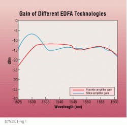
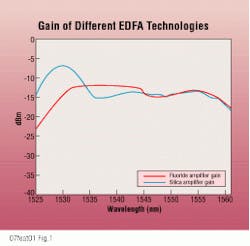
Two predominant edfa technologies are commercially available today: the silica-based amplifier and the fluoride-based amplifier. Both feature the same general internal structure but differ in the host fiber used for the erbium dopant. The silica-based edfa has been available for several years and gained early market acceptance due to its low noise characteristics and wide amplification bandwidth. Both edfa technologies provide adequate amplification across the entire 1525- to 1560-nm erbium passband (see Fig. 1). However, the silica edfa gain curve is not quite as flat.
Because of its design, an edfa contributes a finite amount of noise to the amplified signal, resulting in signal-to-noise degradation and limiting the practical distance between electrical regeneration. The silica edfa boasts a noise figure of approximately 5 dB, only slightly higher than the theoretical quantum limit of 3 dB. For this reason, the silica edfa is widely deployed in booster amplifier and receive pre-preamplifier applications, which tend to be somewhat noise-sensitive.
The edfa was developed as a means to displace the need for costly electrical regeneration of an optical signal. Carriers realized savings not only by reducing the amount of time-division multiplexing equipment required, but often by eliminating the need to build intermediate regenerator sites with their associated power, climate control, maintenance, and security costs.
In recent years, the edfa has evolved into an enabling technology for dense wavelength-division multiplexing (dwdm) as the market demand for capacity has exploded. Through the use of dwdm, carriers have greatly increased the bandwidth capacity of their embedded fiber plant, eliminating the need to invest in more outside plant. In addition, dwdm has allowed carriers access to untapped portions of their existing fiber plant, unlocking bandwidth already in the ground. This has provided much-needed capacity relief while opening opportunities for new revenue streams as legislative reform has created an onslaught of new competitors.
As dwdm technology matured, the number of channels that can be multiplexed has increased. Just a few years ago, 4-channel wavelength-division multiplexing was considered high capacity; today, vendors offer products that multiplex more than 40 channels onto a single fiber. All this multiplexing is not without its costs, however. Each time the number of optical channels on a fiber is doubled, there is a corresponding 3-dB reduction in signal gain. This is where the edfa, with its ability to amplify several optical channels in the erbium passband, makes dwdm possible in today`s networks.
The silica amplifier
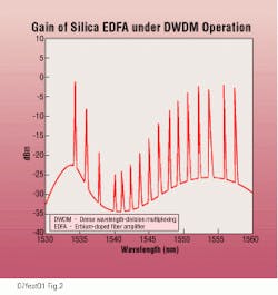
Amplifying a dwdm signal with a traditional silica-based edfa, however, poses some technological problems. Figure 2 illustrates how the gain curve of a dwdm signal--16 channels of OC-48 (2.5 Gbit/sec) in this example--is affected by a series of silica-based edfas. As you can see, some channels retain a relatively strong signal-to-noise ratio (snr--the difference between the highest and lowest parts of the channel gain), whereas others, especially in the 1540-nm region, encounter serious signal-to-noise erosion. This degradation can be so severe, in fact, that these channels no longer offer an adequate snr and become unusable for transmission.
Because of early industry acceptance of silica-based edfas, techniques have been developed that allow these amplifiers to be effectively used for dwdm. One such technique that is commonly employed--bandpass reduction--uses only the upper half of the erbium passband to carry dwdm channels. By filtering out the 1530- to 1542-nm region, carriers are left with a relatively flat, albeit smaller, window in which to multiplex channels. This can lead to some concerns in dwdm applications with extremely high channel counts, however, since very tight channel spacing is required. The resulting dwdm signal has a greater sensitivity to nonlinear effects such as four-wave mixing. Also, considering the current state of filtering technology, there is often a price premium to be paid to recover such narrowly spaced channels.
A second technique used to flatten the dwdm gain curve of silica-based edfas is to selectively attenuate each optical channel at its input to produce a flatter, more consistent snr at the far end. This technique is usually required even with the bandpass reduction technique mentioned previously.
As a channel`s power is adjusted, however, every other dwdm channel on the fiber is also affected, making system optimization a complex, iterative process. This becomes even more difficult and time-consuming when the bit rates of channels being added or removed differ. OC-192 (10-Gbit/sec) transmission, for instance, requires a snr 6 dB greater than that of an OC-48 signal; therefore, additional power must be added to the OC-192 signal to compensate.
Vendors recognize this inherent complexity and are integrating self-optimization algorithms into the network element. This greatly benefits the carrier, since optical balancing is required not only at system initialization but any time channel count or channel bit rate is modified.
The fluoride amplifier
In an effort to increase the usable bandwidth and sidestep the gain-flattening complexities associated with silica edfas, several vendors have turned to commercializing the fluoride-based edfa. Fluoride can absorb more erbium than silica and produces a flatter gain across the entire erbium passband, opening up the 1530- to 1542-nm region to dwdm channels. In addition, since there is a smaller degree of gain differential between each channel, the requisite optical power balancing is much simpler.
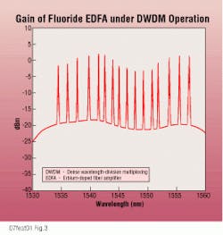
Figure 3 illustrates the performance of the fluoride edfa under dwdm conditions similar to the silica edfa shown in Fig. 2. The dwdm channels can be multiplexed over the entire erbium passband, and each channel exhibits comparable snr performance. This, in turn, greatly simplifies the process of power balancing, making the fluoride edfa easier to reprovision as channels are added or dropped.
The one performance drawback of the fluoride edfa is its higher noise figure--the result of being pumped at 1480 nm. Silica amplifiers use a pump wavelength of 980 nm, which is inefficient with fluoride fiber due to excited-state absorption. This higher noise figure results in performance implications when designing extremely long regenerator-to-regenerator spans that use cascaded edfas. There are ways to overcome this inherent weakness, and vendors are beginning to offer next-generation fluoride edfas that provide both a flat gain and a low noise figure.
As carriers have turned to dwdm to relieve capacity bottlenecks, they have taken the first steps toward implementing the optical layer. This new layer will provide high-level routing and restoration of optical signals while the traditional Synchronous Optical Network (Sonet) layer will provide the multiplexing and customer interface functions.
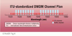
To provide interoperability between the Sonet and optical layers, the International Telecommunication Union has standardized a dwdm channel plan with 100-GHz spacing and a reference frequency of 193.1 THz. This channel plan allows carriers to migrate their Sonet layer products into the optical layer. Figure 4 illustrates how 16 channels can be multiplexed into the erbium passband using conservative 200-GHz spacing.
Sonet technology has evolved to the point that OC-192 transmission is on the verge of widespread network acceptance. Transporting this higher-bit-rate signal in the optical layer has implications for edfa technology selection. First, due to information bandwidth requirements and available laser tolerances, it may not be possible to multiplex OC-192 channels any tighter than at 100-GHz intervals. Carriers, therefore, need to look to edfa technologies that use as much of the available erbium passband as possible. Second, OC-192 transmission requires an snr at least 6 dB higher than that of OC-48 transmission. Without the use of gain-flattened edfa technologies, this snr limit may restrict carriers from carrying OC-192 channels.
As we have seen, both predominant edfa technologies offer advantages and disadvantages to carriers considering evolution toward the optical layer. Regardless of the edfa technology employed, however, the gain flatness of an amplifier becomes the critical performance factor to be considered. Without flat gain, some dwdm channels become unusable, and the efficiency gains promised by the optical layer are diminished. As carriers look to today`s technologies to meet network demands, it is imperative that their choices do not limit the opportunities to evolve to tomorrow`s network. q
Thomas Fuerst is a lightwave product marketing manager at Alcatel Telecom, Richardson, TX.Fig. 4. This figure shows the use of 16-channel dense wavelength-division multiplexing via the International Telecommunication Union channel plan. Even with a conservative spacing of 200 GHz, the plan easily accommodates the channels.
