Chromatic dispersion tolerances get tighter
Dispersion measurement tools can come to the rescue of 10- and 40-Gbit/sec network architects.
A.J. Barlow
PerkinElmer Optoelectronics
To meet the worldwide demand for bandwidth, optical fiber communication data rates have migrated from 2.5 Gbits/sec to 10 Gbits/sec and, in the future, to 40 Gbits/sec. At these new rates, the hitherto almost imperceptible limitations of the fiber transmission medium now take on a vital importance. These limitations include parameters such as polarization mode dispersion (PMD) and in particular chromatic dispersion (CD).
The need to build long-haul and metro fiber links with 10- and 40-Gbit/sec data rates has required a sea change in approach to the management of both PMD [1] and CD. [2] For example, the DWDM and 10-Gbit/sec revolution has seen the reduction of fiber PMD by specialized fiber manufacturing techniques. More recently, active PMD compensation techniques have emerged. Massive efforts have also been expended to manage CD using dispersion compensation technologies and special fibers with certain CD characteristics.
Coupled to the push for 10 and 40 Gbits/sec has been a corresponding effort to develop testing procedures and technologies to verify that dispersion is under control. PMD measurements on installed links (whether legacy or new fiber) are now commonplace and vital to confirming the suitability of a link for the proposed data rate. In this case, PMD is generally screened to not exceed certain values. CD testing is becoming routine, driven both by the higher data rates and by the availability of cost-effective portable dispersion test equipment. In this case, dispersion is quantified to allow compensation to be added or confirmed. The impact of amplified links, where regeneration is carried out only after ~1,000 km of fiber, has been to exacerbate the dispersion issues still further. Ironically, as data rates climb the use of amplifiers to "go the distance" increases. This further drives the need to measure complete amplified networks. [3]
Despite the recent market downturn, which will inevitably delay the adoption of 40-Gbits/sec systems, the development of such systems by the major system houses continues. An integral part of this effort is to develop adequate dispersion measurement and control strategies. In this article we focus on CD measurements in a network construction/maintenance context. We take an up-to-date look at the CD issue from a dispersion compensation engineering and measurement standpoint and examine the issues involved as data rates increase to 10 and 40 Gbits/sec.
Limitations
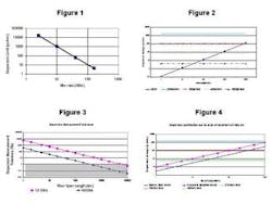
First we examine the well-known limitations posed by dispersion. Increasing the data rate reduces the duration of the data bit period and therefore the maximum tolerable amount of time dispersion. While PMD tolerance is proportional only to bit rate [1], the maximum tolerable CD is proportional to the square of the bit rate [2], depending slightly on data format (e.g., NRZ, RZ, etc.), as illustrated in Figure 1.
Therefore, the migration from 2.5 Gbits/sec to 10 Gbits/sec involves a four-fold decrease in bit period and PMD tolerance, but a 16<-fold decrease in the tolerable CD. Thus, while PMD control is one thing, CD control is a massively more significant issue, aided it has to be said, by the fact that CD is not a statistically varying parameter like PMD. Another 16-fold decrease in CD is needed to go from 10 Gbits/sec to 40 Gbits/sec.
To handle the effects of CD, we can exploit its linear and additive properties. "Dispersion compensation" refers to the removal of dispersion from a link by deliberately adding an equal and opposite amount of dispersion into the link either in lumped (e.g., via dispersion compensation modules -- DCMs) or in distributed form (e.g., via fibers in the link with dispersion "matched" to other sections of the link). With DWDM, this compensation must be performed over all of the wavelength channels, and a fully dispersion managed and slope managed link is required.
In many cases, fiber measurement is used to aid the process of determining the link CD and subsequent selection of DCM module, etc. This will be explored later in this article. However, a number of other issues must be considered in order to accurately implement dispersion compensation.
CD compensation issues
CD measurement is critical to overall system set up: Obviously, the compensation must be set up sufficiently well to provide a net system dispersion as close to zero as possible, but certainly within the allowable dispersion margin (see above). Often, as we shall discuss in more detail below, this can only be achieved using actual measurements of dispersion in the link at various stages of its commissioning.
DWDM system bandwidth: The dispersion compensation must be applied for all available DWDM channels, typically covering the entire C-band and/or L-band. This requires the slope to be managed and dispersion data to be collected over a wide wavelength range. Ideally, any dispersion measurement equipment used must cover the entire DWDM channel space.
DWDM channel definition: If the system under test incorporates DWDM add/drop multiplexers to define the wavelength channels optically, then the dispersion measurement equipment must collect data and be able to cope with the gaps between DWDM bands. In addition, if the dispersion test equipment uses a delay data fit to obtain dispersion, careful fit control and selection is needed to work within the defined bands and avoid these gaps. These points will require considerable skill on the part of the operator in many instances. Direct dispersion measurement using the differential phase shift method [4] may be more applicable in these cases because data fitting is not required, and dispersion data need only be collected within the defined bands.
Dispersion is temperature-sensitive: Long un-regenerated links carrying high bit rates over many wavelengths will exacerbate the problem of dispersion. Once the system is compensated for dispersion, dispersion change with temperature (~0.002 psec/nm/km in NZDF fiber) may still be a concern, for example in a transcontinental aerial link. Figure 2 shows the dispersion change in psec/nm for a 50 degree Celsius operating temperature range compared to the dispersion limit. Clearly, beyond 1,000 km and 40 Gbits/sec some kind of continuous dispersion tuning is required to keep dispersion in check. At more modest bit rates and/or link lengths, the temperature sensitivity represents a variable dispersion contribution that eats into the tolerable dispersion margin. This means that the original compensation must be more finely set up to allow for the variability. Again, measurement will aid the correct setting.
Dispersion measurement accuracy must be sufficient: It is often desirable to increase the span length between amplifiers to minimize amplifier count or to reduce the effects of amplified spontaneous emissions, etc. As the amount of dispersion increases with the link length, a finer relative balance of the compensation must be made. This demands a higher relative accuracy and precision of the measured dispersion. This is given by:
Percentage Dispersion accuracy = 100*Dispersion Tolerance/(Fiber Dispersion* span length) %
Multiple amplifiers add erbium fiber dispersion to the system: The inclusion of fiber amplifiers containing short lengths of erbium-doped fiber into fiber links has greatly increased the capabilities of communication systems. While they have effectively removed the loss limitation in fibers, several well-known issues relating to the amplifier noise (e.g., non-linear effects due to the high optical powers) must also be handled. Less well known is the issue of CD in the erbium fiber. [4] The dispersion is strongly wavelength dependent, with a peak at 1535 nm. Moreover, the dispersion value varies strongly with pump power. Chromatic dispersion in the amplifier is typically 3 psec/nm and so multiple amplifiers will contribute significant dispersion (Figure 4).
After 30 amplifiers the dispersion within the erbium fiber used reaches the 40-Gbit/sec dispersion limit. Clearly, to avoid unnecessary reduction of the dispersion margin, it is advisable to confirm total dispersion in the final system after amplifiers have been equalized at their operating pump powers and to compensate for fiber, DCMs, amplifiers, and all other components in-line for each channel.
Amplifiers' internal components add more CD to the system: Fiber amplifiers contain several fiber components aside from the erbium gain fiber itself. Typical components are isolators, couplers, and gain-flattening filters. These components will contribute even more CD than the erbium fiber within the amplifier itself (see above). Allowing a total chromatic dispersion budget in the amplifier block of 10 psec/nm we obtain the upper magenta curve in Figure 4. Here, after only five amplifiers, the amplifier block CD contribution reaches the 40-Gbit/sec dispersion limit, and significantly, is a substantial portion of the 10-Gbit/sec CD tolerance after 10 amplifiers. Measuring the total chromatic dispersion will allow final dispersion tuning to be made with sufficient accuracy.
Dispersion compensation strategies and measurements
Typically, correctly compensating the dispersion within a fiber link means that the fiber dispersion must first be known to some degree of accuracy [5]. Then a DCM module is inserted to suit the amount of dispersion in the fiber. Once the DCM is added, a follow-up measurement of the total dispersion is often made to confirm the compensation has worked.
When upgrading legacy networks, the fiber type or origin may be unknown and CD data unavailable. Therefore, a measurement is really the only way to quantify what is in the ground. Even if the data is available, a final CD measurement is useful to keep track of the dispersion margin, especially at 10 Gbits/sec and 40 Gbits/sec.
Other scenarios rely on the assumed fiber dispersion value from the fiber or cable manufacturer. However, this approach is generally considered unlikely to yield sufficient accuracy of compensation to meet the tighter dispersion limit at 10 Gbits/sec and 40 Gbits/sec.
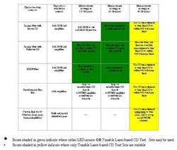
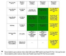
Various dispersion compensation scenarios are reviewed in the Table. In the Table, the colored areas show where measuring the fiber dispersion is either extremely advantageous or vital to the accuracy of the compensation process. Evidently, the tighter tolerance on dispersion at 10 and 40 Gbits/sec has a direct effect on the required strategy for dispersion compensation. We conclude that 40-Gbit/sec long-haul systems virtually cannot be built without using dispersion measurement in some form on the installed link, while at 10 Gbits/sec, measuring the dispersion is highly effective.
Dispersion measurement equipment
As we have seen, dispersion compensation is simple in principle but somewhat more difficult to implement in real situations. Dispersion margin, wider DWDM bandwidths, longer fiber spans, and multiple amplifiers between regenerators or DCMs all conspire to increase the complexity of the task.
Measuring the dispersion as part of the compensation strategy allows this complexity to be broken down into manageable parts. For example, the amplifiers in a long-haul 40-Gbit/sec system must be tuned for channel gain, gain flatness, ASE contour, suppression of non-linear effects, etc. Once this is done, the actual dispersion of the link with the amplifiers in their operating state can be measured separately and the final dispersion compensation tuned for optimum dispersion margin. Measuring the dispersion allows an additional degree of freedom in the amplifier setup.
Obviously, the dispersion measurement equipment itself plays a vital role. It must be of sufficient accuracy to allow meaningful compensation work to be carried out. In many cases, measuring the fiber spans between amplifier sites may suffice, and in the situation of a broadband fiber link, most typical LED-based equipment will suffice (green boxes on table). In general however, the equipment must have sufficient dynamic range to cope with the full span loss.
As soon as amplified or DWDM systems are to be measured as a link, then it is generally necessary to adopt one of the newer tunable laser-based dispersion measurement test sets (yellow boxes on table). [5] These offer superior accuracy under conditions of narrow DWDM bands and limited erbium bandwidth. Moreover, these systems must be designed to operate when the amplifier chain may still be undergoing adjustment and are therefore operating at sub-optimal levels of optical signal-to-noise ratio (OSNR). By design, the leading portable optical network chromatic dispersion test sets have special electronic filtering to remove the effects of ASE and are capable of working to specification with OSNR as low as 4 dB in 0.1 nm bandwidth.
It is clear that 40-Gbit/sec systems will require dispersion measurements of high accuracy just to be built efficiently. At 10 Gbits/sec, dispersion measurement eases the system setup as well. The arguments developed above are borne out by experience with real system upgrades, new link construction, and proposed link design/installation approaches.
Test equipment vendors are now offering truly portable and cost-effective laser-based network CD test sets to more easily allow system builders and installers to achieve ever-higher data rates and longer spans (e.g., with Raman amplification). These test sets permit the correct local dispersion characteristics to be set up in order to suppress non-linear effects, but simultaneously with very low total dispersion within the allowed dispersion margin. In essence, the use of the test set allows full flexibility of the dispersion management design and dispersion map to be exploited to optimize the system as a whole for all the limiting factors.
Network chromatic dispersion test sets provide vital data for optical system upgrade and build programs. Most of these test sets consist of a separate transmitter and receiver unit placed at each end of the test fiber. In some cases, any transmitter can operate with any receiver, so that by using one pair at each end of a link/network, CD measurement can be performed in either direction simply by mixing and matching the units. Flexibility and robustness to the link operating conditions make these test sets extremely valuable in real-life network commissioning.
References
1. IEC 61282-3 TR3 (formerly 61283-3) "Guidelines for the calculation of Polarization Mode Dispersion in fiber optic systems."
2. IEC 61282-5 TR3 (formerly 61283-3) "Guidelines to accommodate and compensate for dispersion in fiber optic systems."
3. J. Barlow, "Dispersion measurement in state-of-the-art optical networks," NFOEC, July 2001, Session C8.
4. R. Cella and J. Wood, "Measurement of Chromatic Dispersion in Erbium-doped Fiber Using Low Coherence Interferometry," OFMC'01, Sept 2001, Cambridge, UK, pp 207-210.
5. J. Barlow. " Measuring Chromatic Dispersion helps Optimize network performance," WDM Solutions, March 2001, pp 121-125.
A.J. Barlow is technology and development manager, PerkinElmer Optoelectronics (Wokingham, UK). He has been active in the field of fiber measurements for almost 20 years, especially in CD and PMD measurements in both production and field/network test environments. Dr. Barlow also conducts regular in-house customer training courses, holds several patents in fiber-optics technology, and was instrumental in the development of low birefringence "spun" fibers.
Figure 1. Maximum dispersion margin (psec/nm) for a 1-dB power penalty in NRZ systems for various bit rates.
Figure 2. Dispersion change with temperature (50 degrees C) eventually exceeds the dispersion limit for long-haul high bit-rate systems.
Figure 3. Dispersion measurement tolerance (accuracy) versus fiber span length.
Figure 4. Dispersion contribution from a chain of erbium amplifiers at 1535 nm.

