Multipath interference in all-optical networks
As optical networks move to higher speeds while reducing electrical conversions, optical effects such as multipath interference become even more significant issues.
Dr. Kreshnik Angoni
Due to the technical and cost advantages, fiber-optic networks are headed toward a 10- to 40-Gbits/sec, all-optical scenario. In this picture, which doesn't contain electrical regeneration sites, transmission quality is determined largely by the optical effects in the fiber.
Distributed Raman amplification is the main technology that opens the door to all-optical transmission in long-haul and ultra-long-haul systems. Multipath interference (MPI) is the optical effect that limits the gain level in systems that make use of Raman amplification.
Some physics
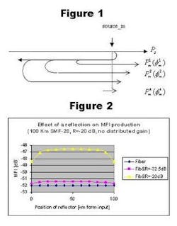
Rayleigh backscattering and local reflections are the physical source for MPI. In Figure 1, the primary source is a reflection or a Rayleigh backscattering while the secondary backscattering is only Rayleigh backscattering. In general, the related calculation are based on double reflected optical power because those reflected four, six or more times are very low.
The interference effect is built at the level of the primary source. For further propagation there is no change in the phase difference between the main beam and its secondary components. As long as the length of fiber is less than the "coherence length of signal," there is coherent MPI. In optical fiber (transmission or dispersion compensating), due to the much longer lengths, MPI is practically built by incoherent interference. The MPI coefficient is defined as:
Due to the isolators at amplifying sites, the MPI produced in a span is independent of other system components. Under the assumption of missing MPI from other spans, the signal and scattered power are equally attenuated and amplified until the receiver input. Applying this reasoning for each span, it turns out that for an n-spans system the total MPI is:
Another source for MPI is the EDFA. Real networks may contain many EDFAs, and the related total MPI therefore becomes important. A low level of MPI is produced in optical filtering devices (mux/demux, etc.). As the number of these devices is small, in general, the related MPI is negligible. So, a more explicit expression for total MPI is
One may find out that, in a general scenario, MPI_system must be lower that -27 dB so that the related penalty on Q-factor is lower that 0.1 dB. At this point, the significance of precise MPI calculation and the factors that influence its level becomes clear.
MPI in systems without distributed gain
In transmission fiber or dispersion compensating fiber, the distributed reflectance is an inherent characteristic, defined by the coefficient of Rayleigh backscattering. For a given fiber type, the quantity of MPI produced by its distributed reflectivity depends on the length. Meanwhile, the presence of local reflection may change in a dramatic way the MPI production in the same piece of fiber.
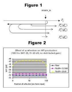
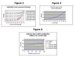
The graph in Figure 2 describes the effect of a dirty PC connector (its reflectivity is increased form R=-32.5 dB to -20 dB) on MPI production in a SMF-28 span. (All such data in this article refer to the most affected channel in the L-band.) Figure 3 shows the sensitivity of MPI production versus connector reflection and the MPI produced by EDFAs in a 1600-km system based on SMF-28 fiber.
When referring to the 0.1-dB penalty, one may see that:
- if the MPI produced by the EDFA is -40 dB, the system cannot meet the requirement even with very high quality reflectors.
- if MPI per EDFA is -45 dB, the system can meet the requirement by using PC reflectors (R=-35 to -30 dB), but it is very close to acceptable limits.
- safe system function needs EDFAs with MPI production lower that -48 dB.
Figure 4 shows that the production of MPI increases quickly with distributed gain in fiber and explains why this effect is the main obstacle to the use of high gains. Even at 12-14 dB MPI increases by ~5 dB.
Meanwhile, the reflections effect is more problematic. Figure 4 shows that this effect is negligible for reflections lower than -45 dB, but it may increase MPI by about 9 dB if the end connector is damaged (R=-25 dB).
Summary
The precise calculation of MPI produced by the system is the only way to define the related requirements for fiber, EDFA, connectors, etc. For a system without distributed gain it reveals the allowed margins on connector and splice reflections and for the possibility of system upgrade. In general, clean PC connectors (R~-35 dB) are good enough for this kind of system. For a system with distributed gain one must use super PC connectors (R < -45 dB).
In general, at the end region of a span there are additional splices. Their location and relative deterioration is not a big issue for systems without distributed gain. However, these splices pose critical problems for systems with distributed gain. Meanwhile, the performance of isolators is an issue for all optical systems. Nowadays, the continuous control of reflections levels is obligatory for long-haul and ultra-long-haul systems.
Dr. Kreshnik Angoni is a physicist. He offers professional consultations on linear and non-linear physical phenomena in optical systems. He has many years of R&D experience in optics applications (communications, spectroscopy, etc.) and has worked for different employers (universities, research institutes, and private companies). Last year he was a senior optical system designer at Ceyba Inc. He can be reached at 514-344-1907 or by e-mail at[email protected].


