Meeting the Unique Test Challenges of FTTx Deployment
Introduction
Rapid growth of fiber optic networks has resulted in an explosion of improved services to residential consumers. Fiber to the home (FTTH or FTTx) reaches more than 200 million homes globally, 20 million of which are in the United States1. As telecommunications companies replace aging copper networks with fiber, they are able to deliver more bandwidth, reliability, flexibility and security to end-users.
FTTH passive optical networks (PONs) are increasingly being deployed to provide optical fiber’s bandwidth advantages at a lower cost than point-to-point architecture affords. However, PONs present unique test challenges when installing and maintaining an FTTH network. This article provides an overview of FTTx PON architectures, identifies test challenges unique to FTTx PONs, and describes optical tests recommended to verify or troubleshoot FTTx PONs, including in-service (live) PONs.
FTTH Network Architectures
FTTH networks may be deployed using either point-to-point or point-to-multipoint network architecture.
Point-to-point architecture provides a dedicated fiber connection from a service provider’s central office (CO) to each subscriber’s premise. A point-to-point architecture also requires dedicated electro-optics for each subscriber at both CO and the customer premise.
Switched Ethernet architecture may be used to aggregate traffic from multiple subscribers before backhauling it to the CO over a single fiber. However, this requires electrical power at the Ethernet switch, and still requires dedicated optics at both the switch and customer premise for each subscriber.
One of two PON technologies is commonly deployed in point-to-multipoint networks: ITU-T defined Gigabit-capable passive optical network (GPON) or IEEE-specified Ethernet passive optical network (EPON).
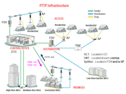
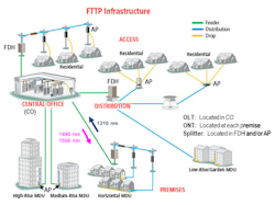
In both GPON and EPON networks, active electronics are located only at the end-points of the PON, reducing network cost and increasing network reliability. An optical line terminal (OLT) residing in the carrier’s CO communicates across the passive optical distribution network (ODN) to optical network terminals (ONTs) located at subscribers’ premises (see Figure 1).
In the ODN, a single feeder fiber connects the CO to a pedestal- or pole-mounted fiber distribution hub (FDH). The FDH may be located in a neighborhood or the entry level of a multi-dwelling unit (MDU).
In single splitter PON architectures, a single 1x32, 1x64 or 1x128 splitter is installed at the FDH. A feeder fiber connects the central office to the splitter at the FDH. This passive splitter separates the downstream signal into 32, 64 or 128 copies. Each of the many splitter ports is then connected through distribution fibers to pedestal- or pole-mounted Access Point (AP) terminals. A drop fiber connects each AP terminal to an ONT installed at each subscriber’s premise.
A PON’s trunk-and-branch architecture reduces the amount of fiber required. Additionally, the downstream signal is broadcast to all attached subscribers, so a single downstream transmitter serves multiple customers. In the upstream direction, subscribers are assigned unique time slots in which to transmit, with the signals from the subscribers combined at the passive splitter and sent to the CO over the single feeder fiber. Consequently, a single CO receiver also serves multiple customers.
Traffic on the network
Both GPON and EPON deliver voice, data and IP video signals downstream using 1490 nm wavelength. An optional video overlay may be transmitted downstream at 1550 nm. Voice and data are communicated upstream from the ONT on the same fiber using 1310 nm wavelength.
Downstream signals are optically divided at the splitter into multiple identical signals. The optical power of each signal is reduced by the split ratio plus some excess insertion loss. For example, the optical power level through a 1x32 splitter is reduced by approximately 16 dB—slightly more than 10 x log(32).
Multiple subscribers may simultaneously wish to send data upstream to the CO. Since all ONTs use the same 1310 nm upstream wavelength, time division multiple access (TDMA) is utilized to prevent multiple ONTs from sending signals at the same time. With TDMA, the OLT assigns each ONT unique time slots during which it can send a burst of data in the upstream direction, preventing multiple ONTs from transmitting simultaneously.
FTTH PON Testing Overview (installation, activation & maintenance)
Proper testing is a critical part of installing, activating and maintaining a PON. While most components are tested during the manufacturing process, they are tested again after splicing and installation of splitters and access terminals. Field testing is required to ensure no excess loss or reflectance has been introduced due to micro-bends in installed fiber, poor splices, macro-bends in splice closures or access terminals, or dirty, damaged or improperly seated connectors. If not detected and corrected, excess loss or reflectance often results in poor network performance. Performance may initially seem acceptable, but over time, transmission errors may begin to increase long before the need for any maintenance activity would normally be expected.
Tests commonly used to verify optical links include the following:
· Connector end-face inspection and cleaning
· Insertion loss test
· Optical return loss test
· Optical time domain reflectometry (OTDR)
Connector contamination and damage are the most common causes of poor optical network performance, according to a recent study by NTT-Advanced Technology2. Connector inspection and cleaning during installation and maintenance are among the most effective methods for ensuring an optical network will deliver expected performance. Connector inspection is typically performed using an optical microscope. To prevent accidental eye damage when inspecting fibers potentially carrying live traffic, a video microscope images the connector end-face and displays the magnified image on a handheld display. Dirt, debris or damage is easily detected. Images may be captured before and after cleaning, then compared for any variation. Captured images may be analyzed for pass/fail by applying criteria specified in IEC 61300-3-353.
An insertion loss test measures the end-to-end loss of the installed link by injecting light with a known power level and wavelength at one end, and measuring the received power level output from the other end. The measured difference between the transmitted and received power levels indicates the optical loss through the network. Insertion loss is considered acceptable when the measured loss level is lower than the budgeted loss level.
An optical return loss test injects light with known wavelength and power level into one end and measures the power level returned to that same end. The difference between the injected power level and the measured return level is the return loss. Return loss is considered acceptable when it is higher than the minimum allowed return loss. A low return loss value (below 35 dB) is often an indication of one or more sources of excess reflection in the network under test, typically due to dirty or damaged connectors, a fiber break, or an air gap at poorly mated connectors.
Since optical network loss is wavelength-dependent, insertion and return loss testing is typically performed using wavelengths at or near those which will be used during network operation. In the case of FTTx PONs, insertion and return loss testing at 1310 nm, 1490 nm and 1550 nm may be required. In practice, testing is often performed only at 1310 nm and 1550 nm, reasonably expecting loss and return loss at 1490 nm to be between the levels measured at 1310 nm and 1550 nm.
If the loss and return loss measured at each wavelength are within the levels budgeted for the link, the optical network may be considered ready for activation. However, in many cases, the network operator requires the network to be more fully documented using an optical time domain reflectometer (OTDR).
An OTDR scans a fiber from one end to measure the length, loss and optical return loss of an optical network. It also locates and measures reflective and non-reflective events in the network due to connectors, splices, micro- or macro-bends, splitters or faults.
Operating like a radar, an OTDR injects narrow pulses of light into the fiber under test. As each pulse travels down the fiber, imperfections in the fiber scatter some of the light, with some of this Rayleigh-scattered light being guided back up the fiber.
Optical pulses and backscatter experience some loss as they traverse a mated connector pair, mostly due to imperfect alignment between the two connectors. By measuring the difference between backscatter levels before and after the connection, the OTDR is able to measure the loss across each connection.
A Fresnel reflection is generated whenever the pulse encounters a mismatch in the index-of-refraction, usually at a mated connector. An air gap at a poorly mated connector or an open connector end will generate a strong reflection. This reflected energy is also guided back up the fiber. (Note: The ends of APC connectors are angled to ensure that light is reflected off the end-face at such an angle that it is not captured and guided back up the fiber.)
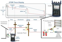
The OTDR measures the level of returned backscatter and reflections versus time, converts time-of-flight into distance, and creates a trace which plots changes in backscattered and reflected light levels versus fiber length. Losses due to connectors or macro-bends appear as abrupt changes in the backscatter signal level. Reflections due to connectors, air gaps and open ends appear as spikes in the OTDR trace.
To simplify results interpretation, newer OTDRs analyze the trace to automatically detect, measure and identify network events creating a link map displaying each of the detected events using an icon to indicate event type and pass/fail status, along with the location, loss and reflectance of each event.
By analyzing the captured trace, the OTDR can also measure end-to-end link length, insertion loss and ORL.
Insertion loss and ORL testing each provide a single numeric value which can be compared to network-specific limits to determine if the optical plant is within acceptable performance values. However, when unacceptable or marginal values are found, insertion or return loss tests using source and power meter cannot locate the source of the problem. While an OTDR also measures link loss and ORL, an OTDR can additionally locate the sources of excess loss and reflections, reporting the distance to each high loss or high reflectance event.
FTTx PONs present unique test challenges
FTTx PONs typically utilize wavelength-division-multiplexing to support upstream and downstream traffic over a single fiber. This, combined with the point-to-multipoint architecture of an FTTx PON, creates several testing challenges not found in simpler point-to-point optical networks.
When the PON is first installed but not yet activated, end-to-end insertion loss testing may be performed from the OLT to each ONT (or vice versa), providing a point-to-point loss measurement through the splitter. From the OLT end, an optical return loss measurement with the splitter installed provides a measure of return loss from the feeder fiber as well as all of the attached distribution and drop fibers. If any open connectors are present due to unused splitter ports, they will generate strong reflections. If the open connectors are not angled and the reflections are guided back up the fiber to the OLT, poor return loss results will be seen, but the return loss test set will not be able to determine the source of these high reflections.
If an OTDR is used to scan the PON from the OLT end, it will generate a normal trace from the OLT to the splitter. At the splitter, the downstream pulses from the OTDR are split with reduced power pulses simultaneously propagating down each of the attached distribution and drop fibers. Backscatter and reflections from these pulses are guided back up the fibers in the upstream direction, merging at the splitter, then propagating back to the OTDR. At the OTDR, the combined signals from each of the splitter legs appear as overlapping backscatter and reflections, making it impossible to determine which leg is responsible for an excess reflection or loss.
By contrast, if the OTDR is used to scan the fiber from each ONT, it produces a trace showing only the losses and reflections of the link from that ONT to the OLT, including the high loss event through the splitter. For this reason, OTDR testing of FTTx PON distribution and drop fibers is usually performed only from the ONT end. The feeder fiber (from OLT to splitter) is best tested from the OLT end, since small splice and connector losses are more accurately measured when tested without having to look through the high loss of the splitter.
Since OTDR results are very different when testing from OLT and ONT ends, it is not possible to bi-directionally average traces obtained from opposite ends of an FTTx PON.
When a fault occurs on a point-to-point network, service is immediately disrupted. Consequently, disconnecting one end to locate the fault using an OTDR does not create a service disruption.
An in-service FTTx PON presents a very different scenario. If a fault occurs on the distribution or drop fiber connecting the splitter to one subscriber, that subscriber loses service while all others remain in-service. Obviously, one can access the fiber at the out-of-service ONT without creating an additional service disruption. However, injecting an upstream OTDR test signal at 1310, 1490 or 1550 nm could interfere with in-service signals upstream from the splitter. Furthermore, downstream 1490 and 1550 nm signals may still be received at the out-of-service ONT, interfering with the OTDR’s measurement circuitry.
The solution to this problem is a Live PON OTDR, such as AFL’s FLX380-303, with the following capabilities:
· Equip the OTDR with a 1625 or 1650 nm laser, which is out-of-band relative to the PON’s operational wavelengths of 1310, 1490 and 1550 nm.
· Equip the OTDR with a filtered detector to eliminate interference from the downstream 1490 and/or 1550 nm live traffic signals.
· Include a PON Power Meter in the OTDR, enabling it to detect and report the presence and measure the level of downstream 1490 and/or 1550 nm traffic.
· Ensure that the OTDR prevents the user from initiating upstream OTDR tests at 1310, 1490 or 1550 nm when in-service PON signals are detected, while still allowing out-of-band testing to be performed at 1625 or 1650 nm.
Which tests should be performed, when and where?
Optical testing is typically performed at various points in a network’s lifetime:
· Installation verification testing: Occurs as the network is being constructed or after network installation is complete, but before the network is activated. This is usually when the most complete testing is performed, and may include insertion and return loss testing as well as OTDR testing. Pass/fail criteria may be applied to end-to-end length, loss and ORL results, as well as to individual event loss and reflectance measurements for splices, connectors and splitters. Formal reports may be generated, including measured values, OTDR traces, pass/fail criteria and pass/fail results.
· Maintenance troubleshooting: Performed as needed when service outages occur, and typically requires rapid response to restore service as quickly as possible. Troubleshooting may also require non-disruptive fiber identification to ensure in-service fibers are not disconnected. Additionally, maintenance personnel might require a visual fault locator (VFL) to precisely pinpoint the location of breaks or macro-bends in splice or access enclosures.
To address both FTTH PON installation verification and maintenance troubleshooting needs, AFL’s handheld FLX380-303 includes 1310/1550/1625 nm OTDR with LinkMap, integrated PON power meter, optical source, optical power meter and visual fault locator.
Summary
Passive optical networks are being deployed worldwide to more cost-effectively deliver higher bandwidth broadband services to subscribers. FTTx PONs present technicians with unique installation verification and maintenance troubleshooting challenges. These challenges are effectively overcome when technicians understand FTTx PON architecture, and are equipped with test tools designed to address the unique test requirements of FTTx PONs. For recommendations on FTTH PON testing, including a detailed procedure for troubleshooting live PONs, download AFL’s white paper “Meeting the Unique Test Challenges of FTTx Deployment.”
Notes:
1Fiber to the Home Council
2NTT – Advanced Technology; http://www.bicsi.org/uploadedFiles/PDFs/Presentations/Fibre%20Optic%20Connector.pdf
3IEC-61300-3-35, Fibre optic interconnecting devices and passive components – Basic test and measurement procedures – Part 3-35: Examinations and measurements – Fibre optic connector endface visual and automated inspection, 2009-11.
About Michael Scholten
Michael is a Sr. Product Marketing Manager at AFL, one of the world's leading fiber optic manufacturers. The company's diverse product portfolio includes fibre optic cable, transmission and substation accessories, outside plant equipment, connectors, fusion splicers, test equipment and training. AFL's service portfolio includes market-leading positions with the foremost communications companies supporting OEM, outside plant, enterprise and wireless areas.


