Optical measurements support 40-Gbit/sec design efforts
Test equipment for 40-Gbit/sec system design applications may require a new spin on old methods.
BRIAN REICH, Tektronix Inc.
Each new breakthrough in optical transmission bandwidth is more than just a milestone; it is also a steppingstone-a point of departure for the next advancement. Today's optical networks are reliably delivering 10-Gbit/sec data rates, but there is no rest for equipment designers and network engineers. They are already climbing toward the next plateau: the 40-Gbit/sec data rates being used for long-haul and submarine applications.
Although the destination is clearly in view, the path to get there is not straight and level. As data rates escalate, new optical circuit behaviors challenge designers to create new paradigms for characterizing optical signals. Most of these are related to the ever-narrowing pulse widths that come with the increase in frequency (that is, higher bandwidths and faster data rates). Phenomena that had little impact at slower data rates (polarization mode dispersion, for example) suddenly have become roadblocks on the path to 40-Gbit/sec optical signal transmission. Optical components and systems must achieve new levels of signal-to-noise performance, linearity, and power efficiency to get past these roadblocks.
The new requirements are challenging the state of technology in electronics, optics, fiber physics, and measurement. Confronted with the task of developing new 40-Gbit/sec equipment, designers are living the punch line of an old joke: "Watch out for that last step-it's a big one."Optical measurement tools are certain to be an enabling force in the development of 40-Gbit/sec optical-network elements. Innovations in sampling techniques, eye-pattern analysis, signal generation, and dispersion measurement will support designers as they characterize signals composed of tighter wavelengths, picoseconds of jitter, and increasingly low optical power levels.
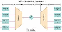
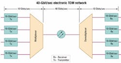
The emerging 40-Gbit/sec architecture is a hybrid arrangement made up of 10-Gbit/sec transmit and receive elements paired with 40-Gbit/sec fiber media, as shown in the simplified network in Figure 1. The difficulty of designing semiconductor devices that can process packets at 40-Gbit/sec rates has spawned an interim configuration that consists of four 10-Gbit/sec transmit elements multiplexed to form one 40-Gbit/sec transmission. That is known as electronic TDM (ETDM). At the far end, the packets are demultiplexed and distributed among four 10-Gbit/sec receivers.
Note that the same 40-Gbit/sec result can be achieved by multiplexing 16 channels of data at 2.5 Gbits/sec (OC-48/STM-16). For the sake of clarity, the ensuing discussion in this article will concentrate on the 10-Gbit/sec approach.
To keep pace with network users' unending hunger for bandwidth, 40-Gbit/sec architecture will eventually employ both ETDM and DWDM techniques. At that point, each core network fiber will carry multiple 40-Gbit/sec channels at various wavelengths.
Physics and fiber optics conspire, it seems, to make 40-Gbit/sec transmission technology a challenge for designers. As stated previously, optical characteristics that had little impact at lower data rates suddenly become make-or-break issues for 40-Gbit/sec signals. One of the most important issues is polarization mode dispersion (PMD), and designers need to characterize, measure, and quantify PMD to successfully develop new 40-Gbit/sec transmission systems.
Dispersion is the tendency of an optical pulse to widen as it travels through fiber. The amount of dispersion tends to be a fixed quantity rather than a proportion of the pulse width. In the "old days," (two years ago!) frequencies were lower and pulse widths were broader and farther apart. Pulses could be compromised by some dispersion without encroaching on their neighbors.
At 40 Gbits/sec, however, pulse width and spacing are too narrow to tolerate any dispersion at all. Each bit position occupies only 25 psec. When a pulse widens due to dispersion, it can change the apparent data state of neighboring bit positions, creating errors. Multiply that scenario a few billion times over, and dispersion can make it almost impossible to extract a meaningful optical signal at the receiving end.
PMD occurs when the optical signal's two polarization modes shift with respect to each other as they travel down a non-ideal fiber medium. Here, "non-ideal" is defined as "not perfectly circular." The receiver sees the two modes arriving at different times and perceives the effect as dispersion.
PMD is inconsistent in its effect, varying from one transmission to the next. It has been said that PMD is the biggest barrier to achieving satisfactory transmission distances with 40-Gbit/ sec signals.
Another type of dispersion, chromatic dispersion, results from another fiber imperfection: its tendency to impart differing delays to different wavelengths. In the real world of imperfect oscillators, filters, and amplifiers, signals are made up of a band of frequencies (wavelengths), not just one ideal center frequency. Wavelengths at each edge of the band experience different delay effects as they pass through the fiber. Again the effect is a widening of the pulses that carry the data. Chromatic dispersion is a special challenge for emerging 40-Gbit/sec DWDM designs, where its impact increases out of proportion to the 4x bandwidth increase between 10 Gbits/sec and 40 Gbits/sec.
The standards for 40-Gbit/sec transmission protocols are not yet engraved in stone. One issue that remains unresolved is the choice of pulse formats. Two formats are under consideration: non-return to zero (NRZ) and return to zero (RZ). Most likely, both will coexist in the final ITU specifications. Companies designing network elements for 40-Gbit/sec transmission are currently experimenting with both formats, as well as forward error correction schemes that increase the standard data rates by 7% or 25%.
The RZ format is a promising solution for the non-linear behavior of transmitted optical signals. When 40-Gbit/sec optical signals are amplified enough to be transmitted over long distances, they begin to suffer from effects like four-wave mixing and cross-phase modulation.Fundamentally, the RZ format has up to two edges in every cycle of operation, while the NRZ format has just one. On an oscilloscope display, the RZ signal looks like a 2x high-frequency signal when compared to the NRZ signal. The 40-Gbit/sec data rate itself taxes the capability of most test instrumentation, and RZ signals demand even higher bandwidth from the sampling oscilloscopes used to evaluate leading-edge designs.
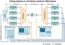
One thing is certain: Development of 40-Gbit/sec technologies cannot proceed without test instrumentation that can accurately capture high-speed signals, analyze dispersion, and track error behavior. Fortunately, the measurement industry offers solutions to meet the needs of designers who are working with the fastest optical signals being generated today. Figure 2 maps some of these solutions onto the 40-Gbit/sec ETDM architecture discussed earlier.
The first requirement is to generate traffic (test signals) to load the network. Supplying data signals to a 40-Gbit/sec network is the job of a programmable SONET/SDH test set that provides data patterns and the necessary physical interface to the system under test (SUT). The requirement is similar to that of a DWDM system in which several 10-Gbit/sec streams are multiplexed into one fiber.
In the 10-Gbit/sec DWDM system, each source is multiplexed to a different wavelength and transmitted at a 10-Gbit/sec clock/data rate. In the ETDM system, the four 10-Gbit/sec sources are phased to transmit sequentially, and the composite transmission rate is a true 40 Gbits/sec on one wavelength. In either case, though, input and output rates are both 10 Gbits/sec. Therefore, the current generation of 10-Gbit/sec test sets is fully prepared to test the emerging crop of 40-Gbit/sec equipment.
There are two approaches to generating the necessary four channels of data. The first of these uses a separate 10-Gbit/sec transmit module in the test set to drive each of the four network elements. The second approach (as seen in Figure 2) uses just one transmit source and a splitter to create the four signals. The first method, though costly in terms of test equipment, may be necessary if the lasers in the transmitter lack the power to drive four data streams. The splitter technique, on the other hand, can provide excellent results without the need to manage four discrete signal sources.
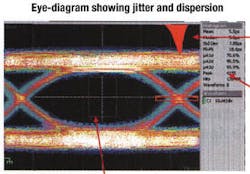
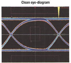
With the traffic of the test set flowing through the network, evaluation of elements such as multiplexers, optical amplifiers, and the fiber itself can begin in earnest. The evaluation process almost always begins with a sampling oscilloscope. It is the best, most versatile solution for capturing eye patterns and for many key optical measurements, including extinction ratio, rise time, and jitter.Eye patterns are the foundation of most optical device analysis. The oscilloscope is triggered synchronously to a data stream made up of random or pseudo-random bits, which is also the input to the sampling module. In an eye-diagram, one screen view embodies all possible transitions: high-to-low and low-to-high for both leading and trailing edges. Figure 3 shows a typical eye-diagram. The "eye" is of course the open area in the center of the screen. The color view shown here is a composite record of many acquisitions, with the brightest areas (white pixels) reflecting the ideal bit pattern for a stable signal. Ideally the eye should be as wide as possible. As jitter or rise-time variations increase, deviance from the ideal signal grows wider and the eye "closes." Modern sampling oscilloscopes can perform statistical analyses such as histograms on the eye pattern. In Figure 3, the panel to the right of the waveform gives quantified readings on jitter performance.
The eye-pattern approach has some limitations. It is not possible to observe the effects of a specific pattern of data, which makes it difficult to isolate inter-symbol interference problems. Moreover, conventional waveform averaging is not possible, because the signal itself tends to average out due to random changes in the pattern. Lastly, random noise and pattern-dependent errors can actually mask each other.
To resolve these problems, some sampling oscilloscopes offer fast acquisition modes that capture each bit position in the data stream separately in a series of sequential acquisitions. Each of these is averaged independently and then put back into its place in the data stream. The result is a clean eye-diagram with the noise averaged out and the underlying waveshapes clearly visible. Figure 4 shows the result.Measurement bandwidth is the key to successful characterization of 40-Gbit/ sec signals, especially where RZ formats are involved. The extremely fast rise and fall times of signals in this format require a higher bandwidth than the basic data rate implies.
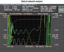
Dispersion measurements are made possible by a special class of instruments known as optical-network analyzers (ONAs). Connected to the fiber or a component in the network, the ONA can detect and measure the telltale pulse spreading that results from both PMD and (where applicable) chromatic dispersion. As a general rule, the average PMD should be kept below 1/10 of the bit period. For a 40-Gbit/sec NRZ signal, the bit period is 25 psec, so the total PMD should be less than 2.5 psec. As PMD increases, usable transmission distance before the signal requires amplification and regeneration decreases.
PMD can arise from both intrinsic and extrinsic factors. Intrinsic effects are unintentionally "built-in" to fiber during its manufacture and include elliptical cores and other asymmetric stresses. These stresses cause the index of one polarized state to differ slightly from the other, creating PMD. The good news for fiber users is that modern process controls have eliminated most of these stress and asymmetry problems, reducing the tendency toward PMD in today's fibers.
But extrinsic factors can still come into play. These may result from twisting or bending the fiber during installation, or from environmental effects such as changes in temperature. Twisting and bending can occur in fibers resting against one another in fiber bundles, when they are organized in splicing trays, or when they are bundled into multiconductor cables. The ONA measures dispersion parameters in the frequency, or wavelength, domain. The instrument must deliver precise resolution and wide dynamic range, two functions that are difficult to reconcile. Like other types of network analyzers, the ONA measures S parameters.Two different ONA architectures are available. The traditional architecture relies on the "pulse method," in which multiple light pulses of different wavelengths are sent through the fiber and captured with a sampling oscilloscope, where their group delay is measured. The second approach is called the "phase shift method." This method uses an RF signal source to intensity-modulate the light sent through the fiber. The instrument determines the SUT phase shift by comparing the phase of the RF signal with that of the SUT output (after an optical-to-electrical conversion). This information is the basis for computations that produce a dispersion figure. The phase-shift method has proven to be the more accurate of the two approaches.
One of the challenges of dispersion measurement is test time. In the case of dispersion characteristics, however, long test times can compromise the outcome of the test; the reason is fiber's response to environmental conditions. Dispersion characteristics change as these conditions change. The leading ONA instruments incorporate a tunable-laser source and an internal optical coupler to enable both transmission and reflection characteristics to be tested simultaneously (in a single sweep). This approach pays off with a huge reduction in test time: from approximately 10 minutes per measurement to about 4 sec. The 4-sec test minimizes the opportunity for environmental conditions to change during the test and influence its outcome. Figure 5 shows a typical ONA results screen.
While PMD is of particular interest in the evolving generation of single-wavelength 40-Gbit/sec equipment designs, chromatic dispersion also has measurable effects. Its impact will increase as DWDM technology is merged into the 40-Gbit/sec realm, where multiple wavelengths must coexist on the same fiber. The ONA is the most efficient solution for measuring both chromatic dispersion and PMD.
The emerging generation of 40-Gbit/ sec optical-network equipment presents much tougher measurement requirements than the 10-Gbit/sec generation that preceded it. Almost every optical and electrical parameter must be within critical tolerances, and picoseconds make a difference. Designers who choose measurement tools that live up to these exacting requirements will do a better, faster job of bringing 40-Gbit/sec optical-network technology to market.
Brian Reich is worldwide business development manager, optical business, at Tektronix Inc. (Beaverton, OR).
