Telecom-device testing in parallel
Higher transmission speeds and multiple channels require parallel bit-error-rate testing in production environments.
BRYAN LORD and RAINER PLITSCHKA, Agilent Technologies
Fiber-optic telecommunications systems provide much higher speeds and capacities than their copper-based predecessors did. Along with these advantages, however, comes the need for increased diligence in preventing bit errors in transmission and reception. Tiny glitches and small amounts of jitter that remained far below the threshold of error only a few years ago can now significantly erode signal accuracy.
Coping with this situation involves two types of solutions. In the component factory, Herculean quality-control efforts can minimize the number of failures. At the customer end, increasingly sophisticated error detection and correction schemes find erroneous data packets and either resend-or request that the transmitter resend-the information or correct it on the fly. The most efficient solution embraces both elements.
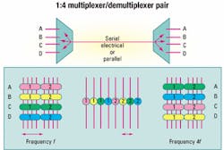
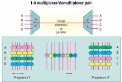
Today's communications systems require multiplexer/demultiplexer pairs on both the transmission and reception lines. Slow-speed parallel signals go through a multiplexer that transmits serial equivalents at high speed. A demultiplexer at the other end reconstructs the original parallel signal.Consider the multiplexer/demultiplexer pair in Figure 1. Low-speed inputs on lines A, B, C, and D are combined into a single data stream at four times the speed. At the other end, the process is reversed. Ideally, the demultiplexed signals proceed along the same lines they used initially. In practice, latency through the device generally prevents the two parallel signal sets from matching precisely. Achieving a match requires some kind of synchronization step.
Transmission speeds have reached stratospheric levels. Gigabit Ethernet, Fibre Channel, InfiniBand, and storage-area networks in LANs reach serial speeds in the 2.5-Gbit/sec range with multiplexing ratios of 1 to 10. Other applications boast even higher speeds. Traditional undersea and terrestrial links in the global network using SONET and SDH protocols run at 10 Gbits/sec, which very soon will rise to 40 Gbits/sec. Here, the multiplexing/demultiplexing ratios range from 1:4 to 1:16.Testing telecommunications devices takes two forms. In the laboratory, test activities must characterize devices completely. Analysis includes a wide range of factors, including bit-error rate (BER), eye-opening (the "eye" is a voltage-versus-time plot of a repetitive waveform), the relationship between clock timing and parallel data, setup-and-hold times, latency through the device, and so on. Design engineers also examine the consequences of reductions in signal amplitudes or power-supply voltages to ensure that those conditions do not erode device performance.
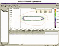
Such elaborate measurement schemes are very time-consuming. Determining the eye-opening, for example, requires knowing the size of the opening at specific BERs. Figure 2 shows the results of BER measurements throughout the eye area, connecting those points where the results are the same. The outermost ring defines the limits corresponding to a BER of 10-5, the next ring in shows a 10-6 BER, and so on. The device's specification determines which ring represents the "correct" opening.
During manufacturing, test goals are quite different. Here, we do not look for a complete picture of device performance. Instead, test determines that if the device is "good enough," does it meet specifications? The task corresponding to the measurements in Figure 2 examines whether the BER falls below a predetermined maximum at the minimum permitted eye-opening. This time, test engineers select a limited number of points (at least six) to define the minimum eye area and measure BERs at those points. If those measurements do not exceed the specified maximum, then the eye-opening is larger than necessary, and the device passes the test. This "good enough" approach drastically reduces test times, helping to ensure adequate throughput to meet production demands.
Performing the tests, however, brings with it considerable challenges. Traditionally, device test employs a "loopback" approach. Testing a demultiplexer, for example, requires placing a proven or "golden" multiplexer on the parallel side. Parallel outputs from the demultiplexer are fed into the multiplexer, permitting a telecommunications single-channel BER tester (BERT) to verify both devices. Alternatively, a bit pattern on the parallel side of the multiplexer is fed into the demultiplexer as a serial bitstream.
Testing the parallel output of the demultiplexer, however, presents its own difficulties. Using a single-channel BERT and a radio-frequency matrix allows testers to step through the parallel output signal one channel at a time. The time required for such a test, perhaps inconvenient on the lab bench, is intolerable for production. Examining the channels individually precludes testing real-world data. Testing for conditions such as ground bounce and thermal loading requires examining more than one channel at a time. The availability of a proven device is uncertain, at best. Any problems will show up as a failure of the device under test. The accuracy of characterization testing in particular suffers from the presence of additional (and suspect) silicon.
Testing devices by stimulating and observing more than one channel at a time offers significant advantages. This method of testing can examine all parallel inputs and outputs simultaneously. Classic pseudo-random bit sequences (PRBSs) allow testing of the serial channels, but pseudo-random word sequences enable the measurement of bits in parallel. This approach automatically synchronizes input and output patterns at word boundaries, making the test easier and more effective.
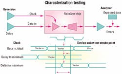
As shown in Figure 3, characterization testing can determine setup-and-hold time constraints. Moving the output data stream closer to the clock in 1- or 2-psec increments will eventually produce an output error. The point at which that occurs defines the minimum permissible time and represents the device's hold time. Similarly, closing the gap between the input pattern and the clock will reveal the minimum device setup time.Adding parallel capability to this test provides a wealth of new information. Moving the channels simultaneously, and individually, allows the test engineer to look for the specific location that fails first. Perhaps a cabling problem increases certain propagation delays. At the board level, different routing lengths may cause different response times from the device, possibly increasing BERs. Tweaking voltage levels on any or all channels can simulate changing conditions that may occur in the field.
Production testing requires looking at the eye-diagram at a minimum of six points; moving quickly through those six points may take 2-3 sec. Suppose, however, that we are looking at the output of a 10-Gbit/sec demultiplexer containing 16 channels running at 622 Mbits/sec. A parallel tester can test all 16 channels in the same time it takes to test a single channel, drastically reducing test time.
Parallel testing can also find performance problems and identify sources of bit errors that escape the traditional ap proach. Although all signal channels often run at the same speed, this is not a system constraint. The channels are in fact independent of one another. One concern on today's super fast devices is the prevalence of crosstalk: the presence of a spurious signal along with the correct one on a device channel. Crosstalk can cause errors in transmission and reception.Consider the testing of parallel optical transceivers. Conventional multiple serial testing will not reveal crosstalk problems. Running adjacent test channels in parallel at slightly different frequencies, however, will uncover such problems without any time penalty. The phase shift caused by the frequency difference between the real and crosstalk signals on any channel will cause the faster signal to walk transitions through the symbol of the slower channel. The speed of this "walk" depends only on the difference between the two frequencies. Crosstalk within the device or on the bus into the device shows up as BER failures.
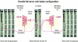
Consider testing a typical 10-channel multiplexer/demultiplexer pair. The test involves applying a pseudo-random word sequence (in parallel) to the device's parallel inputs and examining the pseudo-random bit sequence that comes at 10 times the speed from the multiplexed output. In the same way, we send a known bit sequence into the serial input of the demultiplexer and examine the word sequence that comes out.
Figure 4 shows the appropriate configuration for testing this device on a parallel BERT. The module on the left will provide a 125-MHz clock to the multiplexer. Since the 10 data channels on the multiplexer run at 250 Mbits/sec, the clock signal internally performs a 2x conversion. Multiplying the resulting clock by 10 produces the 2.5-Gbit/sec signal speed of the multiplexed output, and we have to analyze the multiplexer at that speed. Similarly, a 2.5-Gbit/sec generator feeds the demultiplexer, producing 10 demultiplexed channels running at 250 Mbits/sec.
To actually conduct the multiplexer test, the 125-MHz signal coming from the first clock group feeds into an external trigger. An integer multiplied from 1 to 255, internal to the clock module, provides the 2.5 Gbits for analysis.
A sequence editor sets up the procedure to synchronize the input and output signals. An analyzer looks at the data coming in and synchronizes the output to it. Once the signals are in sync, the actual test, which can include an infinite signal loop, begins.
Rising production levels and device complexities demand new alternatives to traditional device testing. For laboratory characterization, where test time is largely irrelevant, traditional serial-only techniques will provide most of the information necessary to assess device quality and reliability. In production, however, meeting throughput and production-level requirements will mean turning to parallel test approaches. Otherwise, manufacturing operations will have to resort to disproportionate investments in capital equipment, additional infrastructure, and people. The only other option is to convince device designers to slow the pace of development.
Bryan Lord is a business development engineer at Agilent Technologies (Colorado Springs, CO), and Rainer Plitschka is an applications consultant, based in Böeblingen, Germany.Whatever the purpose, all articles, product announcements, and advertisements in Lightwave can be reprinted to suit your informational needs.
For information, contact
Kathleen McIntosh at:
(603) 891-9203,
fax (603) 891-0587, or
e-mail: [email protected].
