Proper ER measurement improves performance
The definition and measurement of extinction ratio (ER) stimulates confusion and extensive dialog in several sectors of the industry. Having a common means of defining and characterizing ER reduces the variation between designers, design validators, and manufacturers across continents and between companies. The careful choice of measurement equipment to match the transmitter being tested will save users time in testing, allowing them to focus on their designs and transmitter yields.
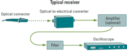
The basic block diagram of the equipment used to measure ER varies little between commercial receivers and custom-designed equipment. Let’s walk through the function of each block shown in the Figure.
The optical interface is designed for ease of connection through commercial connectors and the proper type of optical fiber, which delivers the signal to the optical-to-electrical converter (O2E). The O2E provides an electrical current proportional to the optical power received. It may have an amplifier built into the housing or the receiver may have a separate amplifier following the O2E to increase the sensitivity of the receiver, which is particularly useful for analyzing low-power signals. The amplifier needs to have sufficient bandwidth to cleanly pass the higher-order harmonics of the data rate received, requiring high linearity. These are normally transimpedance amplifiers (TIAs) to convert the current of the O2E output to the 50-Ω characteristic impedance of most high-frequency transmission lines and the inputs of the last item in the chain: the oscilloscope.The oscilloscope is most commonly a sampling unit. Some real time oscilloscopes provide partial characterization of eye-diagrams, though they usually lack an easy means to include a compliance filter. Modular oscilloscopes provide more flexibility, allowing the user to exchange optical receivers as different devices need to be tested. Recently introduced receivers cover a wide range of optical wavelengths and serial data rates, thereby reducing the number of receivers the user needs to purchase.
The measurement receiver is affected by several parameters, including linearity, noise, response of filter and RF path, bandwidth, and the ability to calibrate out the effects of the instrumentation. Let’s consider each of these factors and how they interrelate to affect the measurements.
As in other amplifier designs, linearity is a measure of how well the amplifier tracks the input electrical signal from the O2E. Higher linearity provides more accurate measurement of optical power. The linearity can be characterized and stored in a lookup table to be used during measurements though at the risk of slightly slowing measurement times.
Noise determines the lowest signal level that can be measured, and noise normally can be characterized directly by the receiver. A related figure-of-merit for receiver performance is sensitivity, which assesses the ability of the receiver to discern the “1” level from the “0” level as the signal level diminishes. As that happens, the histograms overlap more, making difficult the separation of the 0 from the 1 level. A more sensitive receiver will provide a cleaner eye-diagram and more accurate measurements in nearly every test condition.
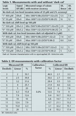
Noise is a function of temperature, and most amplifiers are designed to be relatively insensitive to temperature changes. As the value of the ER for a transmitter increases, the 0 level becomes smaller and smaller until it approaches the noise level of the receiver and ultimately limits the smallest signal that can be measured (sensitivity). At these low levels of power or high levels of ER, the small drift of a well-designed amplifier still affects the reported result. For the most accurate ER measurements, the user needs to compensate for this drift through receiver characterization with no signal applied, often known as “dark cal.” That is quickly performed by turning off the optical signal to the receiver, performing the dark cal, then reapplying the optical signal. Consider the example in Table 1 to see the effects of these factors.
Table 1 demonstrates that the variability of the measured ER becomes much narrower when using dark cal. Note also that the magnitude of the ER worsens quickly as the logic levels are shifted upward. That is a key driver for obtaining the smaller values for the 0 level.
The response of the compliance filter, the insertion loss of the RF path, and the AC and DC gain of the amplifier can affect the measured ER. Most standards require the use of a compliance filter, normally a fourth-order Bessel Thomson with a very tight compliance window. Deviations from this window affect the DC and AC gains and the ER results.1 Most wideband amplifiers are constructed of gallium arsenide ICs with DC gain not exactly matching the low-frequency AC gain, increasing the offset.
Deviations of the AC gain, even within the compliance window, may subtly affect the shape of the eye-diagram and the ER results. The AC gain is affected by the non-ideal response of the amplifier, sampler, and filter and is further complicated by the different response curves between the RF cables, filter, and switches.
The receiver designer also considers the bandwidth of the oscilloscope, assuring that the bandwidth is adequate, the bandwidth response is known, and the effect on the compliance window is understood.
Because of differences between designs, brands, models and individual receivers, the user needs to understand the characteristics of their receiver for the most accurate and repeatable results, thus further reducing differences between various groups of designers and users. The user needs to consider a wide range of parameters to optimize the receiver for applications like:
• Optical wavelengths. Short, long, or both.
• Data rates. Low, high, or both.
• Noise/sensitivity. It is desirable to have the receiver noise floor well below the 0 level or to have typical sensitivity at least a few decibels below the power of the measured signal.
• Power range. Powerful transmitters likely don’t require an amplified receiver. Transmitters of moderate and marginal powers require amplification to obtain a clean eye-diagram and credible ER values.
• Dark cal. Ability to quickly characterize the receiver for the condition of no light.
• Data pattern. The receiver either needs to be indifferent to different patterns or the user needs to characterize the receiver for the desired pattern.
• Analog-to-digital quantization error. The analog-to-digital converter in sampling oscilloscopes typically has more bits of resolution than real time scopes, offering an advantage in the sampling circuits.
Once the user has designed or selected the appropriate receiver, how the receiver reacts to the desired range of signals must be understood. The most direct method is to obtain a transmitter with very high ER (well above 25 dB). Some types of lasers can be optimized for ER and produce very clean eye-diagrams. Another method is the use of dual Mach-Zehnder modulators with polarizers on each path to adjust for path variations.
The best receiver is an optical sampling oscilloscope with bandwidth of multiple times the data rate of interest, thus eliminating the effect of the receiver bandwidth or response. The user warms up the receiver for the time specified by the provider, then performs the receiver calibrations. The transmitter with very high ER is then adjusted for the appropriate power range of the receiver, and the signal is fed into the receiver input. The user performs the dark cal immediately before the ER measurement. The value obtained for the receiver then becomes the calibration factor for the receiver.
One alternative method, known as a “transfer standard,” uses a receiver of known ER calibration factor. The value for the desired receiver is determined by the difference when measuring a signal with reasonably high ER (>16 dB).
The above procedure characterizes the receiver for the low-frequency effects of the response of the entire receiver path. The resulting calibration factor is used to adjust the measured value, providing a result with accuracy very close to the uncertainty of the calibration factor. The equation below governs this adjustment for the calibration factor.2 The units of decibels are used to reflect the specifications in industry standards. The units of percentage are chosen to stress the importance of correctly using percentages and decibels in each part of the equation:
ER[corr] = ER[meas]-10*log {1-ER [CF]*10^(ER[meas]/10)},
where ER[corr] = the value in dB adjusted for the ER calibration factor, ER[meas] = the value in dB measured on the sampling oscilloscope, and ER[CF] = the ER calibration factor in percent provided by the user or provider.
Let’s consider an example of how this works using all percentages, starting with the setup conditions:
• The wide-bandwidth optical system has a dynamic range >30 dB.
• The ER of the test signal is 0.2% (27 dB).
Now, let’s determine the receiver calibration factor:
• The ER measured on receiver is 3.4%.
• The calibration factor for the receiver is 3.4% minus 0.2%, or 3.2%.
Next, we measure the eye-diagram of interest:
• The receiver reports an ER of 12.6% (9 dB).
Finally, we adjust the reported result using the calibration factor:
• Subtract the receiver calibration factor of 3.2% from the reported result of 12.6%, for a final ER measured value of 9.4%, or 10.3 dB, which can be compared to the standards specification.
The most capable sampling oscilloscopes and receivers have the ability to automatically adjust the measured value for the calibration factor. Otherwise, the user can perform the calculations manually using the above equation. A sample worksheet appears in Table 2, which shows the adjusted value for one calibration factor and several measured values of ER.Bob Hasenickis product marketing engineer, digital signal analysis, at Agilent Technologies (Santa Rosa, CA).
1. P.O. Andersson and K. Akermark, “Accurate Optical Extinction Ratio Measurements,” IEEE Photonics Technology Letters, Vol. 6, No. 11, November 1994.
2. “Improving the Accuracy of Optical Transceiver Extinction Ratio Measurements,” Agilent Application Note 1550-59, p. 16, April 2005.
Editor’s Note: A companion article by Bob Hasenick, “The Increasing Importance of Extinction Ratio in Telecommunications,” can be found at www.lightwaveonline.com.


