Look both ways before crossing the network
Value-added modules allow competitive carriers with collocation agreements to non-intrusively monitor network performance.
Todd Duberstein
ADC Telecommunications
The driver behind this trend is collocation. Competition has never been keener in the telecommunications marketplace. In this era of deregulation and nonstop technology advances, competitive local-exchange carriers (CLECs) are pushing incumbent local-exchange carriers (ILECs) to provide better service, lower rates, and enhanced offerings. But CLECs still rely on incumbents. Because of high startup costs, staffing, and logistical issues, many CLECs collocate equipment and hook into local-exchange fiber networks from an ILEC's central office. This competition, however friendly, can lead to difficulty when one party needs access for network troubleshooting, especially when it's not clear whose equipment is at fault.
To alleviate some of this conflict, the concept of "collocation hotels" has become fashionable. Owned and operated by independent entities, these carrier-neutral dwellings provide central-office floor space in a single building for many different flavors of service providers. With potentially hundreds of cages separating the equipment and providing security, carriers swap back and forth a multitude of different signals and services through this single office. In theory, cooperation should be improved since everybody is still just leasing space and more or less on equal footing, but ownership of network problems can still lead to territorial disputes.In either environment, a service provider selling a DS-1 (1.544 Mbits/sec), a DS-3 (44.736 Mbits/sec), or any SONET rate to a customer is responsible for that circuit up to the agreed-on demarcation point. Handoff in the optical domain can be accomplished in a number of ways. Generally, fiber-optic patch cords are simply connected to fiber panels or frames, with one provider granted access to the rear, the other to the front. For example, an ILEC hands off OC-12 (622-Mbit/sec) optical bandwidth to an Internet service provider (ISP); the ISP will then split that signal out, and convert it to electrical signals before sending Internet services to various homes.
It goes without saying that service integrity has become extremely important to all parties. As e-mail and other forms of data services have become critical to individuals and corporate enterprises, any significant signal loss or extended downtime cannot be tolerated. Finding a problem before it becomes a hard failure and affects customers does more than prevent loss of business. It gives the service provider flexibility in choosing the best way and best time to address the problem. Thus, many service providers are implementing proactive maintenance practices by using test access points on every fiber at the demarcation point prior to handoff.Testing these handoff points on today's fiber networks provides some unique challenges. A fiber network is by nature a closed system and, unlike its copper cousin, not easy to tap. The first indications of trouble are typically the failure of a signal to show up at its intended destination or when its arrival is either corrupted or attenuated. Even though the current service quality may still be adequate for customer needs, these types of errors often are a forewarning of equipment failure down the road. As a result, an operator may be forced to conduct a labor-intensive hunt to find the source within a buried or otherwise inaccessible loop to avoid future problems.
One approach is to disconnect the connectors from the fiber frame at each suspected point of failure and plug them into an external test device. This procedure is time-consuming and requires that part of the network be taken out of service.
Convenient access to the equipment is another issue. A collocated CLEC in one cage may suspect it is not receiving good signals from the ILEC equipment in another cage. But there's no easy way to log into the ILEC's equipment to make sure. Usually, a few phone calls are required and, with luck, the CLEC can find the one or two people who are familiar with the equipment, then wait for them to go test it. This cost delay and interruption of service while a line is tested is more than an inconvenience; it is a critical obstacle to the evolution of network service and support.
To avoid these types of issues, network operators need a passive, non-intrusive testing solution. Non-intrusive handoff contracts-which specify that if there are non-catastrophic network test issues, the carrier must continue transmitting-is a major trend in this area.
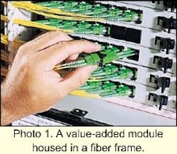
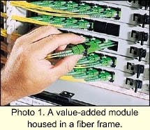
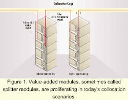
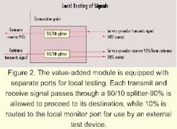
VAMs are finding tremendous acceptance at these critical fiber demarcation points. The modules slide into the fiber frame, and fiber patch cords are installed from each to the network equipment (see Figure 1 and Photo 1). The VAM is equipped with separate ports for local testing. Within the module, each transmit and receive signal passes through a 90/10 splitter; 90/05 splitters are also commonly used. While 90% of the signal is allowed to proceed to its destination, 10% is routed to the local monitor port for use by an external test device. This routing allows local testing of either signal without interruption of service, with test devices having access to the full optical signal-exactly what the customer is getting (see Figure 2).When commissioning a network, test equipment uses this signal to generate a known pattern, which simulates real customer traffic. The pattern is carried on the network or circuit under test, then test equipment at the receive point determines whether the transmission is successful (without errors). At this point, the technician knows that it is functioning correctly and what the levels are supposed to be. Periodic checks will show if power levels are deviating from this norm or if bit-error rates are increasing, indicating a signal degradation associated with the future failure of a laser, connector, splice, or some other network device.
Several vendors supply VAMs, but operators should consider some key differentiators when choosing a module. The first relates to the design and production of the coupler components, which are mounted within the VAM and provide the means for splitting signals with low loss and high reliability. The coupler devices used in the network must have high reliability to guarantee network availability. The mach inery that makes these devices is very expensive, and the techniques used to manufacture with precision are difficult to master.
On top of that, significant pressure exists for fiber component vendors to bring products to market as quickly as possible in high volume. Because of time and technology constraints, many systems vendors do not have the luxury to develop capabilities in-house and are willing to purchase from outside sources or co-develop components with established vendors. As a result, these vendors sacrifice internal control over quality and are sometimes subject to the irregular manufacturing schedules of their suppliers.
Vendors such as ADC that develop the technology and perform production in-house generally are immune to these types of problems. Producing millions of couplers a year allows an in-house vendor to fine-tune the manufacturing equipment, software, and processes to guarantee very high yield, quality, and high reliability in field environments. Compliance with in dustry standards, for high temperature, high humidity, and accelerated aging, such as required by Telcordia Technologies (Bellcore) GR-1209 and GR-1221, British Telecom, Deut sche Telekom, and others, are a standard part of the production process. The Table on page 86 depicts meantime to failure (MTTF) in years for 1x2 couplers, identified by service condition.
An important design consideration when choosing a VAM is the access to the connectors. Dirty connectors are the highest cause of poor performance and the most likely failure points in the network. Thus, periodic cleaning of the connectors is a mandatory requirement. But connector cleaning can present some unique challenges.
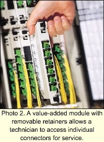
Most VAMs have at least two monitor ports, one each for the transmit and receive circuits. When a connector is cleaned or new circuits are turned up, there is the potential for dust or dirt to enter other connectors within the fiber frame. One solution is an adapter design with removable retainers, which allows access to individual connectors (see Photo 2). This design lets a technician remove the connector, clean it, and put it back in without exposing the other fiber to the risk of breaking and taking down service. In some VAM designs, the adapters are fixed to the sheet metal of the fiber frame, and the only way to get to the connectors is by removing the cover and exposing all circuits to contaminants and potential fiber damage.
Many vendors build performance-monitoring functions into transmission equipment. However, there is a mistaken notion that this function eliminates the need for external test equipment. Performance monitoring is optimized to report what is going on at the transport rate, for example, OC-48 (2.5 Gbits/sec) or OC-192 (10 Gbits/sec). It is very good at detecting major problems such as the complete failure of a transmitter or a fiber cut. But there are a number of failure conditions not detected by performance monitoring:
- Input/output port failure-since this is a physical interface, it is an area with one of the highest failure rates.
- Faulty cabling or dirty fiber connections on long-haul and tributary equipment.
- Sectionalizing or localizing trouble-most monitoring of path errors and alarms is done at the path terminating points within long-haul or metro routes, making it difficult to locate the exact point of the problem. VAMs located at strategic points in the network simplify this process.
- Ownership of only one end of the path terminating equipment. In collocation, a network provider may own only the transmitter or the receiver equipment, not both ends. This makes it impossible to test the end-to-end network. A VAM located at the optical handoff solves this problem.
There are also interoperability issues between multivendor equipment to consider. No regulations exist for standardization on the testing portion of the signal. Therefore, manufacturers may look at bit-error rates in different ways and not communicate this test information to other vendors.
Open-platform test boxes, which can plug into a receiver from brand X or a transmitter from brand Y and look at the overhead, are available. But without a VAM, it is still an intrusive solution and doesn't provide a true picture of the network, only the specific point under test.
There is also a notion that testing can be done using the digital-crossconnect systems (DCSs) employed by some carriers. While DCS equipment does include some testing features, these boxes are geared to the telephony switched network and optimized for DS-1, DS-3, and other electrical signals. Even though the DCS may have an optical input and output, it still only tests a signal comprising electrical signals, and all-optical crossconnect systems are not yet commercially available. Thus, carriers handing off pure optical bandwidth cannot test it through the DCS.
Sometimes network operators don't see the benefit of VAMs until after a serious network failure. That's understandable, especially in the case of startup carriers. VAMs may be perceived as an operations department luxury that doesn't contribute to revenue generation-it costs money and doesn't really do anything except provide an opportunity to test.There are several value propositions to counter these perceptions. There are many ways to look at operations cost, one way being, what is the cost of service going down? If a circuit fails and can be discovered in minutes with a VAM and repaired, customers may not be upset. When service is down for a day or two, as sometimes is the situation with intrusive methods, customers may consider switching to another provider that will guarantee quality of service.
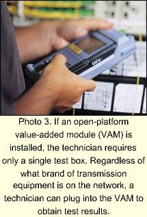
In addition, maintenance costs are reduced. With an open-platform VAM installed, the technician has to carry only a single test box. Regardless of what brand of transmission equipment is on the network, a technician can plug into the VAM to obtain test results (see Photo 3). Moreover, the technician doesn't have to learn the specifics of each piece of transmission equipment-its proprietary software, different testing protocols, etc.Keeping technicians trained and up-to-date on a variety of vendor-specific equipment is expensive. Once technicians are well-trained, their market value increases and retention becomes an issue. As a result, many carriers are adopting modular products that are easy to learn and easy to service. This approach not only brings down operational training costs, it makes it possible to hire less-skilled personnel to work on these networks.
The bottom line is that the combined cost of a VAM and other associated passive termination equipment is less than 1% of the infrastructure service cost needed to deliver a fiber circuit. This one-time cost is miniscule compared to the millions of dollars spent on transmission elements. And yet, the cost savings in problem prevention and customer retention gained through VAMs can be enormous.
With competition at an all-time high in the telecommunications marketplace, network reliability, efficiency, and performance are critical to acquiring and retaining customers. Throw collocation into the mix and five-nines (99.999%) operability is mandatory, even with limited manpower and time. The VAM, when used for non-intrusive access for network testing and monitoring, helps ensure networks are up and running and providing revenue.
Todd Duberstein is a product manager for the fiber-optic division of ADC Telecommunications (Minneapolis).
