Dispersion testing using a femtosecond PMD analyzer
Optical fiber is probably the oldest and most commonly used broadband passive component in telecommunications. Due to the intrinsic birefringent nature of its materials, fiber is polarization-sensitive and consequently disperses the conveyed light. This phenomenon is known as polarization-mode dispersion (PMD) and critically hampers the optical signal. PMD is not the only showstopper, however. There is also the more deterministic wavelength-dependent dispersion known as chromatic dispersion (CD). Therefore, fiber manufacturers want to accurately measure PMD and CD in the fibers they produce.
One approach to PMD testing is to use a femtosecond PMD analyzer. Based on its design and manufacturing, the analyzer's internal optical blocks can be inverted to respond to test needs. The analyzer can be used in two configurations, which are totally equivalent if the device under test (DUT) does not change or move during the measurement. In one configuration, the interferometer precedes the DUT, and in the other, it is placed after the DUT. But if the DUT moves during the test (i.e., exhibiting dynamic phenomenon, which is the case for fiber spools), the two configurations will exhibit two different behaviors.
In the "DUT-interferometer" connection scheme the setup is source, interferometer, polarization state generator (PSG), DUT, and polarimeter. The polarimeter measures the intrinsic PMD and polarization-dependent loss (PDL) of the interferometer along with the characteristics of the DUT.
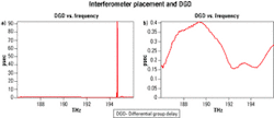
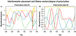
The "interferometer-DUT" configuration—source, PSG, DUT, interferometer, polarimeter—avoids this problem, because the PMD and PDL intrinsic defects of the interferometer are converted into optical power fluctuations, which are not harmful in PMD testing. Consequently, for very low PMD values—typically several tens of femtoseconds—the interferometer-DUT configuration is preferred.In the shown test data, PMD was tested in the same 25.2-km LEAF fiber spool. When the interferometer is placed before the fiber spool, the degree of polarization (DoP) swings with large amplitude and the measurements are not repeatable. The DGD also shows a surge to 90 psec, caused by a rapid movement of the fiber during the test inducing CD, which heavily impacts the results. How can such a discrepancy be explained?
The technique used in the femtosecond PMD analyzer consists of measuring Stokes vectors from the Fourier spectra. This technique is equivalent to using a Fourier transform (FT), or interferometric optical spectrum analyzer (OSA). In an FTOSA, the interferometer and detector are working closely and synchronously: The detector records the correlation signal coming from both arms of the interferometer.
Consider the ideal theoretical case for the DUT-interferometer connection scheme, where the interferometer is polarization-independent and the DUT and PSG do not vary with time—static phenomenon. In this case, the resulting signal Z1(v,t) can be written as:where HPOL(v) is the time-invariant Jones matrix of the polarimeter, HINT(v,t) is the time-dependent Jones matrix of the interferometer—the time dependence is introduced by the moving arm of the interferometer, HDUT(v) is the time-invariant Jones matrix of the DUT, HPSG(v) is the time-invariant Jones matrix of the PSG, and ESRC(v) is the input Jones vector (from the source).
In general, matrices are not commutative. But under precise conditions, the order of some matrices in the above equation can be inverted. Indeed, in this case frequency-dependency does not hamper the commutative property of matrices, while time and polarization dependencies do not allow the matrices to be commuted. Also, two matrices not having any common dependencies can be commuted.
The ideal interferometer does not have any dependencies with respect to polarization and the ideal DUT does not vary with time. Therefore, the interferometer can be inverted with the DUT, and the equation can be rewritten as:Consequently, for the ideal system: Z1(v,t) = Z2(v,t) = Z3(v,t).
In a more realistic system, the interferometer has an intrinsic residual PMD and PDL, inducing a non-negligible polarization dependency. Assume that the DUT does not move or vary during the test, which is the case with most passive components. The impact of the residual PMD and PDL of the interferometer would add up to that of the DUT and alter mostly low PMD values—in the tens-of-femtosecond range. In this case, Z1(v,t) is different from Z2(v,t), because HDUT(v) and HINT(v,t) are polarization-dependent.
Finally, Z2(v,t) is different from Z3(v,t) because HPSG(v) and HINT(v,t) are polarization-dependent. In this last case, the PMD and PDL of the interferometer will combine to the infinite PDL of the PSG to alter the spectral shape of the input source. Since PMD testing is of a differential nature and therefore insensitive to the source shape, the measured PMD values will not be affected by the defects of the interferometer. Which is why this connection scheme is recommended for most passive components.
What happens if the DUT varies in time (e.g., a spool of fiber)? The Jones matrix of the DUT will be written as HDUT(v,t). The mathematical expression Z'sub>1(v,t) characterizing the DUT-interferometer configuration becomes:The theory behind the FTOSA requires that the optical signal be stable in time. If the optical signal fluctuates during the measurement, its resulting spectrum would be distorted and consequently provide faulty measurements. In this case, Z'1(v,t) π Z'2(v,t) π Z'3(v,t), and the described connection configurations are different.
To respect the theory of the FTOSA use the DUT-interferometer configuration with devices that exhibit dynamic variations during the PMD measurements. In this configuration, all optical frequencies, or wavelengths, undergo the dispersion effects of the DUT and interferometer. However, these dispersion effects impact in the same manner on the received signal. On the other hand, in the interferometer-DUT scheme, the interferometer introduces a delay between the signals coming from its optical arms. These delayed signals will undergo different dispersion effects in the DUT.
Testing PMD and primarily DGD rely on a differential technique quantifying how relative spectra (normalized Stokes vectors with respect to optical frequency) are changing from one frequency to the next. It is obvious that if the dispersion effects and variations of the DUT affect all frequencies in the same manner, the detected signals will be perfectly correlated in terms of optical frequency. But if the dispersion and variations of the device impact differently on both optical signals, the resulting signal at the detector will show DGD peaks and a fluctuating degree of polarization, because the optical frequencies are not correlated at the detector.
Michel Leclerc is an R&D engineer and Alain Pham is a product manager at EXFO Electro-Optical Engineering (Quebec City). They acknowledge Bernard Ruchet, EXFO senior optical specialist, for his discussions on the theory of the Fourier transform OSA.


