Test systems using a Golden PLL: Understanding how clock recovery impacts results
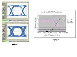
Figure 1: 'Jittery' eye diagram with the clock signal derived from the data as the oscilloscope trigger (above), and with a 'clean' low jitter trigger (below).
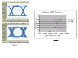
Figure 2: Observed jitter transfer function for a PLL loop bandwidth.
By Greg LeCheminant
Agilent Technologies
Time domain waveform analysis is an integral part of assessing the performance of high-speed digital communications transmitters. Edge speeds, eye amplitude, and eye-mask measurements are examples of common parameters included in communication standards. These measurements are often performed with a high-speed sampling oscilloscope, which requires a reference signal--commonly called a trigger--to anchor the time axis of any measurement. For eye-diagram measurements, it should be some form of clock that is synchronous to the signal being observed.
When measuring transmitters in a laboratory environment, this synchronous clock signal is usually available from the test setup. However, when the transmitter is integrated into a communications system or bus, the data signal itself may be the only signal present. In this situation, a synchronizing signal for oscilloscope triggering may be derived from the data stream through some form of clock extraction. Clock recovery provides the necessary timing reference, but the displayed waveform constructed from a recovered clock can differ significantly from the triggering on a simple clock. Some of these effects are desirable, while others may be unexpected.
As data rates increase, transmitter-timing characteristics, such as jitter, become more difficult to manage. Jitter has been defined as the "deviation of the significant instants of a signal from their ideal positions in time." An oscilloscope displays signal amplitude versus time. For the displayed waveform, time is defined relative to the signal triggering the oscilloscope. If the oscilloscope is triggered with a jitter-free or 'clean' clock signal, the waveform timing performance is relative to this clock signal. If the triggering clock represents ideal timing positions, data edges will be displayed, advanced or retarded from their ideal positions, if they are advanced or retarded relative to the triggering clock. If the triggering signal is derived from the data to be observed, it may be difficult to assess or interpret the true jitter performance. In effect, the signal is being compared to itself. In this scenario, it is possible for displayed signals to be completely absent of jitter, even if significant jitter is present.
The measurements in Figure 1 depict the same signal. The triggering of the oscilloscope accounts for the difference between the waveform displays. When triggering on a clean or low jitter clock (lower waveform), a large amount of jitter is displayed (seen as a thick crossing point at the middle amplitude level of each eye diagram). More jitter is observed when the trigger signal has less jitter. Less jitter is observed when the oscilloscope trigger is derived from the jittery data signal and has more jitter present.
This may seem counterintuitive, but two important points are borne out in the above measurements. First, if one wishes to see all the jitter present on a signal, the oscilloscope must be triggered with a signal that represents the jitter-free condition. An example of this could be characterizing how much jitter a circuit adds to a signal from an instrumentation-grade pattern generator. The ideal triggering signal would then be the pattern generator clock output. Second, if one is forced--or chooses--to trigger the oscilloscope with a signal that contains jitter that is also present on the signal under observation (i.e. a clock derived from the data) then the jitter "common" to both the data and the trigger may not be displayed. If a trigger signal has jitter and the observed signal does not, the oscilloscope will display a jittery signal. Remember, the display is relative to the trigger.
The jitter observed when the oscilloscope is triggered with a clock signal derived from the data will depend on the spectrum of the jitter present on the signal, the design of the clock extraction circuitry, and the amount of timebase delay in the oscilloscope. Clock extraction circuits are often based upon a phase-locked-loop (PLL) architecture, which includes a phase detector and a voltage-controlled oscillator (VCO).
The VCO is phase locked to the incoming data stream and runs at the same rate as the input signal. If the data rate fluctuates, the error voltage from the phase detector will cause the oscillator to shift in frequency and "follow" the data. Adjustment of the loop gain in the PLL structure will control how fast and how far the incoming data can deviate from its nominal rate without preventing the VCO from tracking. This is sometimes referred to as the jitter transfer bandwidth and generally has a low pass effect. (e.g., As the phase fluctuation or jitter increase in frequency, the jitter on the recovered clock will decrease in magnitude.)
Jitter transfer and OJTF
The jitter transfer response measures the amount of jitter present on the recovered clock as a function of the jitter frequency. If this signal is used to trigger an oscilloscope when observing the original data signal, then a jitter transfer plot provides some insight into what jitter can and cannot be observed on the displayed waveform (see Figure 2). When the recovered clock is used to trigger an oscilloscope, the transfer function for the jitter observed on the displayed waveform (observed jitter transfer function or OJTF) is effectively 1 minus the PLL jitter transfer response.
Intuitively, this can be understood as the effect of jitter being common to both the data observed as well as the triggering signal. As long as the jitter is well within the loop bandwidth of the PLL, the jitter on the data stream--relative to the oscilloscope time reference (i.e. the triggering signal)--is zero. While the jitter transfer function of the PLL has a low-pass characteristic, the OJTF follows a high-pass effect. When jitter is at low frequencies, the OJTF function is zero; at high-jitter frequencies the OJTF function goes to unity. An example of a PLL jitter transfer loop response and subsequent OJTF are shown in Figure 2.
Using an extracted clock to trigger an oscilloscope is a strategy used in several communications standards to eliminate low frequency jitter in transmitter waveforms. Since communications receivers are able to track low frequency jitter, transmitters should not be rejected for its presence. The OJTF response is not a simple complement of the loop response; phase must be considered and, depending on the PLL design, the OJTF function can exhibit gain above unity at a range of jitter frequencies. In these areas, the observed jitter can exceed the actual jitter of the data signal. While the original intent may have been to suppress low frequency jitter in a waveform display, an unintended consequence can be amplification of the displayed jitter spectrum just above the loop bandwidth of the PLL. This is a source of jitter measurement error that can be difficult to trace; however, careful design of the PLL loop response can reduce peaking in the OJTF response.
In some clock recovery designs, the PLL loop bandwidth and the subsequent OJTF are dependent on data transition density (how often data transitions from a '0' to a '1' or from a '1' to a '0', with a maximum transition density of 1 occurring when the data sequence is 1010101010....). The PLL gain required to achieve a specific loop bandwidth is reduced as transition density is increased. Thus, for a fixed amount of jitter with significant spectra in the region of the 3-dB bandwidth frequency, jitter measured using a recovered clock trigger from the PLL can vary in magnitude as the transition density changes.
Consider jitter measurements performed with a pseudo-random binary sequence (PRBS), which has a transition density of 50%. The results may differ from a measurement made when the pattern is switched to something with a higher or lower transition density, even though the actual jitter may have remained constant. This reveals another possible source of jitter measurement error for the oscilloscope.
As an example, the PLL loop bandwidth can vary from 1 MHz to 2 MHz as the data transition density is changed from 35 % to 70 %. The resultant OJTF will have a similar shift in the 3-dB high-pass corner frequency. The magnitude of any oscilloscope measurement discrepancy depends on what proportion of the total jitter spectrum lies within the region of the OJTF that changes. In a waveform measurement scenario, this problem can be mitigated if the test system clock extraction circuitry can measure transition density and adjust its gain to achieve a consistent loop bandwidth--and thus maintain the desired OJTF even with a diversity of data patterns and transition densities.
Trigger-to-sample delay
Sampling oscilloscopes experience significant delay between the time the instrument is triggered and the data sample is taken. The minimum delay is typically on the order of 20 ns. This complicates the OJTF function, as its magnitude is dependent on the phase relationship between the PLL frequency response and the phase delay generated by the oscilloscope trigger delay. The trigger delay term of the modified OJTF function becomes significant when it approaches half the period of the jitter.
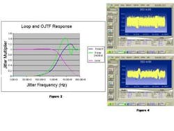
Consider the case where sinusoidal jitter at a specific frequency is applied to the data stream. If the oscilloscope is triggered when the jitter causes data edges to be at their most advanced position, samples taken 20 ns later will likely be made on a signal that has edges at a less advanced state. An extreme case occurs when the phase of the OJTF function is at 180 degrees. At this point, the OJTF potentially reaches a magnitude of two, indicating that the observed jitter is double the actual value. (If the PLL loop bandwidth has any peaking, OJTF can exceed two.) For example, if the jitter is at a frequency of 21 MHz and the oscilloscope delay is 24 ns, the trigger can take place on one extreme of the jitter function (perhaps the most advanced edges) while the sample takes place on the most delayed edges. The relative time shift is equal to the full magnitude of the jitter. Since samples will also be taken in the reverse scenario (trigger on most delayed edges and sampling on the most advanced), the overall observed jitter would be twice the actual. Practically speaking, jitter multiplication will be less than two because the trigger-to-sample phasor and the recovered clock jitter phasor are never at full amplitudes when they are at out of phase with each other (see Figure 3).
Jitter cancellation also can occur. The oscilloscope delay term can cause the trigger point and sample point to be in phase and common-mode out observed jitter. This would occur similar to the above example when the jitter frequency was at any multiple of 42 MHz. The larger the oscilloscope delay, the more significant this phenomenon can be. In the example in Figure 3, jitter cancellation is not significant above the 3-dB rolloff frequency of the PLL as long as the delay term is kept below 24 ns.
Jitter typically is not a single, discrete frequency, and this is another potential source of measurement error to consider when characterizing waveform jitter. The OJTF likely will magnify and attenuate jitter above the PLL bandwidth when significant trigger delay is present.
A very simple technique for correcting any of the above issues involving oscilloscope trigger-to-sample delay is to drive this term to zero. While the internal oscilloscope architecture will not allow the delay term to fall below 20 ns, an equivalent effect can be achieved if the signal path to the oscilloscope input (after clock extraction) has delay equal to the trigger-to-sample delay. This is easily achieved by placing a length of fiber, on the order of six meters, in the signal path when performing optical measurements.
The PLL group delay term can also aggravate measurement accuracy when data patterns exhibit severe changes in transition density. In typical measurement scenarios, if the loop bandwidth of the clock extraction circuitry is increased, less jitter is observed, as the corner of the high-pass OJTF moves up in frequency. However, if transition density changes significantly and quickly, a wide loop bandwidth PLL can be fast enough in its response time such that it will begin to adjust its clock phase to the change in data transition density. Since the correction is not a response to data jitter, the result is an effective jitter mechanism; the recovered clock trigger will have a phase shift that is not also present on the data. In this scenario, a wider PLL bandwidth may exhibit a larger jitter measurement than the narrow PLL bandwidth condition, contrary to what intuitively would be expected. An example of this is shown in Figure 4, where jitter measurements are made on a stress pattern signal with severe changes in transition density. In the first measurement, the loop bandwidth of the PLL was 170 kHz, while the second measurement had a loop bandwidth of 10 MHz.
Note the tabular values for the various jitter components. The total jitter (TJ) value increases 30% as the PLL bandwidth is increased from 170 kHz to 10 MHz. This is driven by a similar change in the inter-symbol interference (ISI) jitter component. (Random jitter (RJ), duty-cycle distortion (DCD), and periodic jitter (PJ) are either insignificant contributors to the total jitter or change insignificantly when the PLL bandwidth is changed). The data-dependent jitter (DDJ), comprising DCD and ISI, is displayed for each bit in the 18944-bit pattern. Note the region (lower plot, 10-MHz loop bandwidth) where there is a significant upward shift in the DDJ value that occurs over a range of several hundred bits. This is a region where the pattern transition density is changing significantly.
Whether this effect is considered a source of measurement error or not depends on the intent of the measurement. Transmitters are often characterized from the perspective of a receiver. If the receiver with which the transmitter is paired has a 10-MHz loop bandwidth in its clock extraction circuitry, the effect can also occur within the receiver timing. It may also generate a phase correction in response to a change in transition density that leads to a bit-error-ratio degradation similar to one caused by an increase in jitter. It can be useful to observe these effects through transmitter characterization. On the other hand, if signal jitter alone is to be observed, then these effects in the instrumentation clock extraction circuitry can yield a pessimistic measurement result. The ability to precisely adjust and control the loop bandwidth of the oscilloscope clock extraction circuit helps to give a deeper understanding of transmitter jitter.
References:
1. Agilent Product Note 86100-5
Greg Le Cheminant is an applications and market development engineer for the Digital Signal Analysis Division of Agilent Technologies (Santa Rosa, CA). His current work involves development of test solutions for high-speed digital communications. He holds a BSEET (1983) and MSEE (1984) from Brigham Young University. He may be reached via the company's Web site at www.agilent.com.


