Monitoring the colors is essential for quality of service
An evolutionary approach to monitoring DWDM systems is to use remote fiber test systems that incorporate existing measurement tools.
Stéphane Chabot and Ghislain LEvesque,
EXFO Electro-Optical Engineering Inc.
Global deregulation of telecommunications providers is creating new competition, rendering quality of service (QoS) an important differentiator in the network decision-making process. In fact, a well-monitored fiber network is already a key strategic advantage; service-level agreements between service providers and key clients or governmental agencies are common. The outcome of all this is simple: If QoS and fault recovery times are not met, huge penalties have to be paid by service providers while customers risk losing service.
In this climate, remote fiber test systems (RFTSs) are viewed as key elements in providing the supervision and maintenance required by fiber networks. Key drivers behind the growing enthusiasm for such systems include the prohibitive cost of losing service, increasing demand for more bandwidth, and a lack of skilled technicians.
A reliable fiber network is not only essential, it is absolutely vital for competitors in the telecommunications field. Loss of service can cost as much as $10,000 per channel per minute. Imagine that an 80-channel system goes down for only five hours; in most cases, the return on an investment of an RFTS is achieved after the first cable break. Moreover, as the bandwidth envelope is pushed even further, out-of-service costs will increase proportionally.The incredible exponential growth of the Internet, along with the proliferation of other new technologies such as video-on-demand, fiber-to-the-home, fiber-to-the-curb, virtual private networks, and wide-area networks (WANs), is fueling a seemingly insatiable need for bandwidth. Fortunately, with the advent of large DWDM, OC-48 (2.5-Gbit/sec), OC-192 (10-Gbit/sec), and soon OC-768 (40-Gbit/sec) networks, system capacity has increased dramatically and a lot more revenue is generated per fiber. Faster systems, however, translate directly into higher risk. Specifications show that more than 128,000 simultaneous phone calls can be handled on a single OC-192 channel; in this environment, network-restoration time suddenly becomes a major issue.
The numbers of qualified people available to maintain fiber networks is limited-and currently decreasing. An RFTS allows companies to maximize the efficiency of their highly skilled personnel on nonredundant tasks.
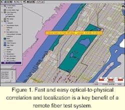
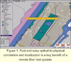
Fast and easy optical-to-physical correlation and localization is a key benefit of an automated system (see Figure 1). The capacity to foresee degradation within the fiber prior to system-performance alteration is another major benefit of fiber monitoring.
Today, RFTSs are not really used for transmission-system fault identification, however. The standard transmission protocol, such as SONET or SDH, is a very powerful tool to identify faults and react in proper time (50-100 msec). SONET switching and network topology-unidirectional path-switched ring or bidirectional line-switched ring-will then heal the network so that no service interruption affects the users.
DWDM does not fit this pattern, however. Although this technology has brought the optical layer to the network hierarchy, protection is not available for DWDM channels, except at the protocol layer (SONET/SDH). Overall spectral supervision is not attainable at the physical layer. As a result, system providers are trying to propose a limited spectral supervision of their DWDM transmission systems. Optical supervisory channels (OSCs) provide limited channel monitoring, mainly because most OSCs today work without really measuring the signal.
Telecommunications operators do not perceive these OSCs as sufficient enough to provide the security level that a good transmission system should demonstrate, especially given the amount of bandwidth going through these systems. Many companies have clearly stated that they will hold off on their DWDM deployment as long as a secure way of monitoring and controlling each DWDM system remains unclear.
The issue is now in the hands of system providers working at the Telecommunications Industry Association level on the proposed FO 2.1.1 standard. These providers are trying to define a common way to solve the problem.DWDM systems have been around only since the mid-'90s, so it is still difficult to identify with certainty the maintenance issues that will arise. High on the list of problems likely to be encountered, however, is an increase in the bit-error rate (BER) of a single transmission channel. This increase could be caused by a drift in the wavelength of a distributed-feedback (DFB) laser source, an uncorrected gain tilt in an erbium-doped fiber amplifier (EDFA), an increase in EDFA noise, or an unexpected variation in the spectral-transmission characteristics of some other component. In the end, single-channel degradation may reach the point where the signal of a particular wavelength is completely lost. Whatever the extent of the loss, field test equipment and procedures must be available to identify the offending part or subsystem quickly and unambiguously.
All of the parameters encountered in the manufacturing, qualification, and installation phases of the network are potential concerns during maintenance. Several of these parameters are direct indicators of possible performance degradation.
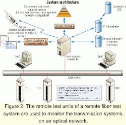
Critical system parameters differ from those of individual components; system parameters must be characterized at each end of the network after everything is assembled and installed on one fi ber. The effects induced by the different components can hardly be foreseeable as components are often increased, added, or removed. Furthermore, a single component may be affected by environmental conditions, physical or optical distances, or other elements such as connectors and patchcords.One of the solutions to this problem is to perform spectral monitoring of one or several colors (channels) in parallel. What better solution than an optical spectrum analyzer (OSA) integrated into an RFTS to provide this monitoring capability? The addition of spectral measurement instruments to the remote test unit of an RFTS provides monitoring of transmission systems (see Figure 2).
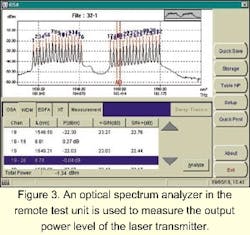
This type of a transmission-system monitoring solution can bring a completely new dimension to fiber supervision. For example, the output power of the DFB should be as high and as stable as possible. High power sources will increase the transmission-span length and reduce the need for amplification. However, very high output power can create undesirable problems on the link's nonlinear effects; therefore, power must be as high as possible but not to the detriment of these effects. This important power limit will be measured during link qualification and should constantly be monitored to avoid signal fault. This measure is taken at the transmitter end following the multiplexer. Since power at the beginning of the link is usually very high-more than 5 dBm-and because the sensitivity of the OSA is better than -75 dBm, a very low signal is needed, which will avoid power loss on the outgoing signal. This setup is also used to monitor central wavelength, channel spacing, and optical signal-to-noise ratio (OSNR) at the same time (see Figure 3).
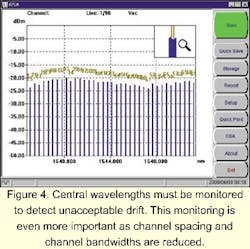
The central wavelength of each channel in the signal is probably the most important single characteristic, given that its accuracy ultimately determines the ability of the source to communicate with the receiver. The central wavelength for each channel must be measured when the network is first installed to ensure that design specifications are met. These values must also be monitored to detect unacceptable drift. The accuracy of central-wavelength measurement increases in importance as channel spacing and channel bandwidths are reduced (see Figure 4).In a switched DWDM optical network, a comprehensive, carefully planned policy is needed to govern wavelength usage, eliminate conflicts in wavelength assignment, and minimize possible interaction between wavelengths. The channel-spacing capability in gigahertz is the interval between two adjacent channels. ITU-T standard bodies have defined a standard channel spacing of 100 GHz-about 0.8 nm-in the ITU-T grid; 50 GHz is also considered in the grid-about 0.4 nm-and eventually lower values will be added. Since a 100-GHz channel separation implies very-narrow-channel bandwidths, spectral drifts in the DFB lasers used as transmission sources can have devastating effects on signal levels at the receiver end. Therefore, source stability and spectral purity are of paramount importance.
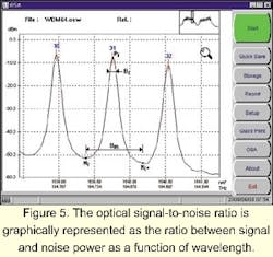
Although the BER is the best single parameter to characterize the performance of a link, it is mainly determined by the OSNR. A drop in the observed OSNR usually accompanies any degradation in transmission quality. There fore, an OSNR measurement for each transmission channel is important during spectral monitoring, routine maintenance, and troubleshooting operations. The OSNR is invariably determined whenever a DWDM system is installed. It characterizes the headroom between the peak power and the noise floor at the receiver end of each channel. The OSNR is an indication of the readability of the received signal, which is of increasing interest as the limits for long-distance applications are pushed further and further.The OSNR is relatively simple to obtain using an OSA. It is the ratio-or difference, when the values are expressed in decibels with reference to 1mW (dBm)-between the peak channel power and the noise power within the channel bandwidth. OSNR is graphically represented as the ratio between signal and noise power as a function of wavelength. The value is typically greater than 40 dB for all channels, measured at the output of the first multiplexer. OSNR is greatly affected by any optical amplifiers in the link and will drop to about 20 dB at the end of the link, depending on the link length, the number of cascaded EDFAs, and the bit rate. An individual EDFA should not degrade the OSNR by more than 3 to 7 dB.
The OSNR must be determined for each populated channel in a WDM system. It is defined as:where Δλ is the interpolation offset equal to or less than one-half the channel spacing (see Figure 5). Deficiencies in OSNR must be dealt with by configuration changes, generally by adding optical amplification at appropriate points in the link. The OSNR is obviously a significant parameter at links between operators as a measure of the quality of the signal supplied.
Optical amplifiers, generally EDFAs, are key to the economical operation of DWDM networks. These devices offer transparent amplification of all channels without regard for the modulation schemes or protocols used in each.
Gain depends on many parameters that, separately or together, can modify device performance. It will vary over time due to temperature changes, local stress, component degradation, and network modifications. Gain is measured as the ratio between the average output and input powers, omitting the contribution of the amplified spontaneous emission (ASE) of the amplifier itself:where G is the gain in dB; Pout (λc) is the average output power at the channel wavelength in milliwatts (mW); PASE (λc) is the ASE power in mW; Pin(λc) is the average input power in mW; and λc is the peak wavelength of the input signal. Gain may also be expressed as a percentage. Typical values for commercial EDFAs are small signal gains, which are represented by the flat region of the gain curve (30 to 40 dB), while spectral widths of 40 nm are typical in nonextended-range (C-band) EDFAs.
Optical noise, more important since the introduction of optical amplifiers in transmission systems, is mainly due to ASE in the EDFAs. Although the manufacturer typically tests the EDFAs individually, it is important to check their performance onsite with all optical channels in operation and all cascaded amplifiers present. ASE noise is particularly significant in some configurations since this phenomenon degrades the OSNR in all optical channels.
The gain curve, which characterizes the gain across the channel spectrum, will change depending on the relative input power of each channel. Thus, the effects of a temporary redistribution of the input power, such as when a channel is added or dropped, must be monitored and controlled in multisignal applications. Gain and gain redistribution can be measured using an OSA. For each channel, input power is measured and the data is stored. The EDFA output is then examined and the channel levels compared with the stored values, giving both the gain and gain distribution among the channels. Usually, noise levels can be checked at the same time.
Modulation rates are measured as gigabits per second. Long-haul communications are presently using the OC-48 (STM-16) 2.5-Gbit/sec and OC-192 (STM-64) 10-Gbit/sec rates; metropolitan communications are usually at much lower rates. Today 40 Gbits/sec (OC-768 or STM-256) is mostly employed in non-WDM point-to-point applications. Demand for higher bandwidth that will require this 40-Gbit/sec rate in WDM applications is expected soon.
High transmission rates can be greatly affected by fiber quality, and more specifically, by polarization-mode dispersion (PMD). Data rates higher than 2.5 Gbits/sec (OC-48 or STM-16) are subject to this effect and require special attention. While some people may think the spectrum-monitoring aspect of RFTS represents a big challenge for test-system manufacturers and that PMD is an even bigger problem, the PMD analyzer may be the next instrument to be incorporated into the RFTS after the OSA.
The receiver's job is to provide the demodulator with the cleanest electrical signal it can extract from the optical signal it receives. The overall performance for a receiver is described by its sensitivity curve, which plots the BER as a function of optical power received for a given data rate. This result, for a given received signal, in turn depends on the receiver's sensitivity, its bandwidth, and any noise it adds to the signal before demodulation. Once the optical power limit has been established, the OSA positioned at the receiver end of the link (before the demultiplexer) will monitor each channel power.
The purpose of system-level monitoring is to demonstrate the overall functionality and integrity of data transmission in all the channels provided. The single most useful parameter characterizing such a system is the OSNR. There are two different points where the OSNR can be measured. At the first site, a single, time-averaged measurement is made at the demultiplexer input. The OSA is used to examine the signal at this point and to determine the OSNR at different spacing, depending on the system vendor's requirements, by comparing the channel peak signal with the noise just outside the channel. An average value exceeding 18 dB is usually acceptable.
Another point where the OSNR can be measured is at the inputs and outputs of each optical amplifier in the link. This value is used to describe overall link performance. This test location becomes crucial when the system contains optical add/drop multiplexers. Gain profile and channel-gain redistribution need to be monitored and adjusted, if necessary. A gain figure exceeding 21 dB with less than 2-dB power difference is generally required for a 2.5-Gbit/sec system.The uniformity of the transmitter power is also of interest. It is generally quoted as the difference in power between the strongest and weakest channels, measured with an OSA at the output of the first optical amplifier fed by the multiplexer. The OSNR should be high at this point->28 dB for a 0.1-nm bandwidth-and the power variation among channels should not exceed 2 dB.
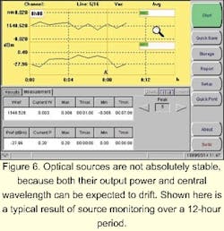
The wavelength or frequency stability of the channels is checked using the OSA. The frequency of each channel must remain within ±5 GHz of the nominal frequency for systems using a channel separation of 50 GHz. Optical sources are not absolutely stable, as both their output power and central wavelength can drift. Figure 6 shows a typical result of source monitoring over a 12-hour period. Drift is caused by such factors as temperature changes, backreflection, and laser-chirp phenomena.
The primary concern with drift is that a signal must remain within the acceptable channel limits at all times, under all operating conditions. Excessive drift may cause the loss of the signal in the affected channel. The drifting source may even spill over into an adjacent channel and have disastrous effects on the information transfer to that channel. Drift must be measured and controlled to avoid loss of data.
There is tremendous interest in monitoring newly installed systems and preventing failure. Largely seen as insufficient by network operators, OSCs cannot provide the QoS required in the competitive world of telecommunications. A more evolutionary approach using real measurement tools within an RFTS can clearly provide a solution that meets everybody's objective, which is to build a safer transmission network.
Stéphane Chabot is outside-plant business unit manager and Ghislain Lèvesque is outside-plant product manager at EXFO Electro-Optical Engineering Inc. (Quebec City, Canada). Chabot can be reached via e-mail at [email protected] and Levesque at [email protected].
