In-band OSNR for ROADMs: A case study
by Francis Audet and Daniel Gariepy
The increasing number of reconfigurable optical add/drop multiplexers (ROADMs) being deployed in today’s networks provides increased flexibility to network operators. At the same time, higher transmission rates (40 Gbits/sec) are making their way into DWDM systems. Combined advances on these two fronts impose tougher requirements on quality of service (QoS) and thus more emphasis has been placed on accurate knowledge of the optical signal-to-noise ratio (OSNR).However, because of these advances, OSNR can no longer be deduced from a simple interpolation of the inter-channel noise level as recommended in the IEC subsystem test procedure 61280-2-9. The inter-channel noise in a multiple ROADM link may be totally uncorrelated to the in-band (at the peak) noise level, and a 40-Gbit/sec signal may have its edges filtered at the same time as the noise, so they coincide with the noise edges. Both issues make OSNR difficult to measure. A few approaches have been proposed (some commercially available) to alleviate these problems and provide a usable OSNR value in a multiple ROADM link.
We present a case study conducted on a Tier 1 network service provider’s ROADM-based network. The study focuses on measurements taken with a spectral-discrimination method implemented in a commercial optical spectrum analyzer (OSA) compared to results obtained with the proposed IEC measurement.
The results presented will compare values obtained for OSNR when using each of the following:
- The IEC standard (IEC 61289- 2-9) approved method.
- Manual out-of-band technique.
- Spectral-discrimination in-band measurement approach.
In a more detailed analysis, peaks for which an alternative validation result was available were evaluated.
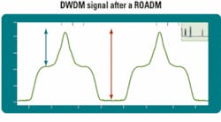
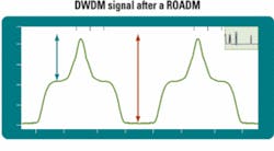
The heart of the ROADM is the wavelength-selective switch (WSS), which is used to select which lambda goes where at any given time. At the output, wavelengths can come from different networks and therefore have different noise contribution. Since any wavelength can be switched to any port, as the wavelengths enter the ROADM, they are demultiplexed. Because filters are wider than the DWDM signal, part of the residual noise goes through. This creates a shoulder-like shape on the filtered wavelength and, at the output of the ROADM, the spectrum may look like that in Fig. 1. The biggest challenge in installing ROADMs is to monitor the impact of the device on the OSNR and what residual signal-to-noise ratio is present at the output.
The standard titled IEC 61280-2-9 Fiber Optic Communication Subsystem Test Procedures Part 2-9: Digital Systems Optical Signal-to-Noise Ratio Measurement for Dense Wavelength-Division Multiplexed Systems defines OSNR measurement as the average between the left and right OSNRs, which are measured as the difference in power between the peak power and the noise at half the distance between the peaks. Unfortunately, this description is no longer appropriate for ROADM-based networks.The example in Fig. 1 illustrates a 100-GHz ROADM and a 10-Gbit/sec transmitter. Even though the automatic OSNR measurement is wrong, an experienced user can manually measure OSNR with visual markers. On a 50-GHz spacing device, even a trained eye can no longer accurately identify the reduced “shoulders” on either side of the peak, but noise is still present in the channel (known as in-band noise). The same remains true for the broader 40-Gbit/sec transmission. So the risk of error is even greater since the noise and signal cannot be discriminated.
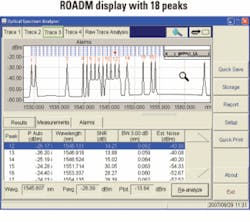
In this example, the system under test had 18 active channels with different OSNR levels that depended on the path followed by each channel. Figure 2 shows the OSA display of the peaks. The graph clearly shows that variable OSNR levels were present and ranged from around 14 dB to 30 dB.
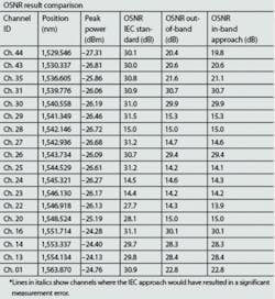
To compare the results of the standardized IEC OSNR measurement method with the in-band technique, another trace was acquired on the same system with the SNR settings in IEC auto mode. A sharp-spectral-response OSA can perform an excellent OSNR measurement out of band, without going through the inter-channel spacing (as standardized by the IEC procedure). This can be done either by placing markers at the shoulder positions or, on some advanced OSAs, by selecting the distance from the peak at which the OSNR is to be calculated (called out-of-band measurements).The table lists the results obtained with each of the methods.
It is important to emphasize once again that the out-of-band approach will provide very good results only if the shoulders are seen on either side of the carrier. With faster modulation, tighter channel spacing, or a different modulation format, this may not always be the case. Thus, an experienced user should determine whether or not a custom analysis will be valid. The in-band analysis, on the other hand, does not require a trained-eye decision.
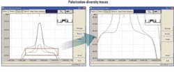
To evaluate the actual OSNR value of a peak where the inter-channel does not work (e.g., Channel 20 at 1,548.5 nm), the saved trace is analyzed. Since in-band measurements work with polarization-diversity detection, two constituting sub-traces are produced.Using the sub-traces and manually evaluating the noise level, a value of -43.2 dBm is obtained for polarization trace B (see Fig. 3; lower curve). This equates to an actual noise level of -40.2 dBm for this peak (3 dB higher, since noise is split in the two polarizations). The peak power was measured at -25.2 dBm (upper curve), which leads to an OSNR value of 15 dB, as compared to 28.1 dB when measured according to the IEC method.
When comparing these results, it can be seen that the in-band measurement is in agreement with the manually obtained value using an alternate technique (based on partial polarization nulling), while the IEC recommended procedure leads to a false result.
A brief validation of the spectral-discrimination in-band OSNR measurement technique was conducted at a Tier 1 network service provider. It was shown that this proprietary in-band measurement technique relying on polarization-diversity detection gives the true ROADM OSNR, whereas it could not be measured using the traditional IEC procedure of inter-channel noise estimation.
This also means that OSAs need to evolve, since all traditional spectrum analyzers are typically based on the IEC procedure for their automated measurements.
Polarization discrimination can be applied using several techniques. Some offer external polarizer and polarization controllers, rendering the setup and test procedure more complex. These hardware parts may be integrated into the OSA, thus providing a one-box approach, but increasing the cost of the OSA per se, basically making it a ROADM-dedicated OSA. Finally, some OSAs have built-in polarization-diversity detection. In these OSAs, a simple software upgrade is required to convert the traditional OSA into a ROADM-ready OSA.Francis Audet is senior product manager and Daniel Gariepy is senior optical specialist at EXFO Electro-Optical Engineering Inc. (www.exfo.com).
