Optical inspection methods for assessing fiber endface workmanship
By John R. Uzzolino and Douglas H. Wilson
Overview
With faulty optical connections a primary cause of network failures, fiber endface inspection is critical. Three methods of endface inspection are reviewed in this article.
Fiber endface workmanship affects the overall performance of an optical fiber system. By some estimates, more than half of all network outages can be traced back to faulty optical connections.
There are basically two classes of workmanship issues that are addressed via optical inspection methods: geometry and cleanliness. Geometry is typically set by the polishing recipe or process and does not change during service. Geometry is verified using an optical interferometric microscope and specialized software that performs fiber endface-specific measurements. The hardware and software used to conduct interferometric measurements are well established and covered by widely accepted standards.
Cleanliness is a term that has been widely accepted to describe both permanent defects (such as scratches, cracks, and pits) and transient defects such as loose contamination (dirt, oils, water, and cleaning solvent residues). Maintaining connector cleanliness is a continuing issue during manufacturing, as the connectors may become damaged or contaminated at any point during the assembly process.
Determining the acceptable level of contamination is difficult due to a lack of accepted standards, as well as the subjectivity, inaccuracy, and lack of repeatability in the inspection process. Inspection is critical for telecom and datacom applications, since excessive defects can cause loss of data or network connectivity. In the case of high-power applications, defects can cause a catastrophic, and perhaps spectacular, failure of the connector.
In this article, we will look at the different ways manufacturing, R&D groups, and end users are currently performing the cleanliness inspection process. Three different 2D optical inspection methods will be reviewed in relation to how well workmanship can be assessed, with the advantages and disadvantages of each method compared. They include manual inspection with an operator and a microscope; semi-automated inspection with an operator, microscope, and a “software assist”; and a fully automated inspection system.
Inspecting where, what, and when
Endface inspection (EFI) is used throughout the supply chain. Cable manufacturing generally has several points of inspection: after polishing, during intermediate testing, and at final inspection. QA departments use EFI for spot inspection, new process or product development, warranty claims, or periodic maintenance. Manufacturing uses inspection for incoming visual inspection, intermediate testing, and final inspection. The end customer uses inspection for incoming QA, periodic maintenance, and liability claims.
The surface defects in a fiber-optic connector consist of scratches, pits, and cracks as well as contamination. Visual inspection can detect scratches, pits, cracks, and loose or fixed contamination, although classification is typically limited to scratches and particles. Scratches are defined as a defect that has a length much greater than the width (generally >30:1 ratio). All other defects and contamination are generally grouped together and called particles or defects.
Scratches are surface features that are most often generated during the polishing process but may also be created during in-service handling of open connections. Cracks are features that appear as ragged lines but are generally much deeper than scratches. Using visual examination of a single image at a given focus, it is difficult to differentiate between scratches and cracks. Pits are permanent features, irregularly shaped areas where material has been removed due to poor handling, the manufacturing process, or damage from contamination present during connector mating.
The potential for permanent damage to a connector endface is a primary reason for the industry expert’s guidance to clean and inspect before mating connectors. Loose contamination can be anything from dirt, dust, oil, or other materials that can generally be removed using a number of cleaning processes. Fixed contamination by definition cannot be removed (except possibly by repolishing) and generally consists of epoxy residue, stains, or embedded particles.
Inspection criteria
Inspection criteria have been developed individually by optical system customers and more recently introduced as international standards, such as the IPC-8497-1. These criteria all have common themes, differing mostly in the exact pass/fail limits. The criteria define concentric zones, centered on the fiber core, that specify regions of varying importance. The number and exact diameter of the zones depends on factors such as the type of fiber (singlemode or multimode) and the type of ferrule.
The inner zone, or core exclusion zone, is the most critical, with the standards allowing no visible scratches or defects for singlemode fibers and at most a few minor defects for multimode fibers. Such defects have been shown to increase insertion loss and reduce return loss, both resulting in degraded performance of the optical link. The standards relax the limits on the other three zones: the cladding, the epoxy zone, and for ceramic and other single-fiber ferruled connectors, the contact zone. The rationale for controlling defects in these regions has more to do with the possibility of migration of defects to the core during subsequent matings of the connector than overall quality of workmanship. It is also a recognition that excessively large particles might prevent proper mating of the connector, leading to degraded return loss.
In certain cases, notably high-power applications, extremely stringent requirements are necessary to prevent catastrophic connector failure due to heat buildup. In these applications, it is especially vital that reliable particle detection, in all zones, is accomplished by the inspection method. These applications may continue to rely on their industry- or customer-specific standards.
Manual, semi-automated, and fully automated inspection
Manual inspection is by far the most common form of inspection in use today. Historically, this was due to the lack of PC-based systems that had sufficient processing power and software with robust enough algorithms to properly detect and classify subtle defects, especially thin, faint scratches. It is considered by many to be very cost effective and generally good enough for many of today’s applications. The process is mechanically simple and relatively fast—although also labor intensive and extremely subjective, and requires a high degree of training to obtain repeatable results.
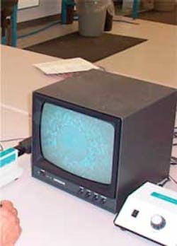
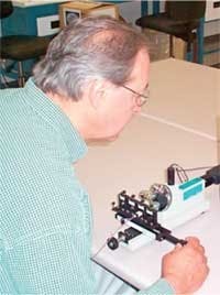
The equipment used to perform manual inspection includes a video fiber microscope, a fixture to hold the connector, and a video monitor. The microscope magnifies the image of the endface, which is then displayed on the monitor, as shown in a typical installation in Photo 1.
The inspector follows a multistep procedure to perform the inspection once the connector is manually loaded:
- adjust the focus
- identify the defects
- determine the size and number of defects within each zone
- determine pass/fail
For field or bulkhead applications, a probe-type microscope, rather than a bench-top microscope, may be used.
Determining the exact size and location of each defect in a repeatable manner is difficult for human operators, even with the aid of a Mylar overlay. Defect detection is dependent on the focus (which is subjectively set by the operator), the inherent resolving power of the microscope, and the contrast of the video monitor used for display. These variables, and the lack of a detailed inspection record, often result in low repeatability among different operators throughout a supply chain. Some studies have measured human inspection repeatability at about 60%.
In the past decade, a number of semi-automated or “software assist” methods have become commercially available. These methods employ the same microscopes as the manual inspection process but use computer-based image processing to analyze the endface. Digital cameras, mostly using USB or FireWire interfaces, eliminate the cost of a frame grabber needed for analog camera-based devices.
Similar to manual inspection, the semi-automated method relies on the operator manually inserting the connector in the fixture, locating the fiber to be inspected (for multifiber connectors such as MPO), and focusing the microscope. Once the operator is satisfied with the image, he or she signals the software to capture the image for analysis. The EFI software collects the image then detects, classifies, measures, and determines the location of defects. Defects are then quantitatively compared to the limits of the selected standard (preprogrammed into the software), including zone information, to determine the pass/fail status of the connector.
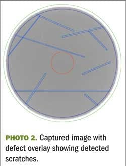
Depending on the quality of the software, the performance of the microscope, and the skill of the operator in focusing and centering the image, these applications have been shown to improve accuracy, repeatability, and reproducibility compared to manual inspection. This method offers a concrete record of the inspection results, including recorded images and a database of defect measurements. Photo 2 shows a fiber with an overlay of the detected scratches.
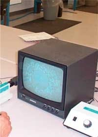
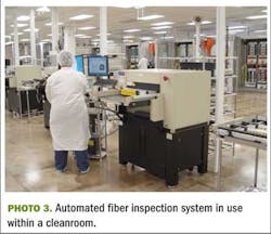
Fully automated systems have been developed that employ the same processing as the semi-automated approach. These systems use computer-controlled motion and, in some cases, multiple resolution cameras to rapidly locate, focus on, and collect images of multiple fibers on multiple connectors within a given unit under test, without any operator assistance (see Photo 3).
The systems eliminate the inherent nonrepeatability of an operator focusing on and positioning the fibers. Furthermore, since the instrument—including software, microscope, lighting, and motion control—is under the control of one manufacturer, the overall system performance can be verified. Inspection repeatability has been consistently reported as greater than 99% on gross defect and greater than 95% on marginal defects. Some automated system users have reported reproducibility across multiple machines testing the same parts at Six Sigma levels on inspection sample sizes in the several millions of fibers tested.
Fully automating the inspection process has significant advantages over both manual and semi-automated inspection. Focus, contrast, and optical calibration are all fully automated with a master fiber and NIST-traceable calibration procedure. Automated inspection improves test accuracy, reduces testing costs, increases test throughput, reduces operator training, obtains process data, and reduces supply chain friction. Also, automated systems will accept a custom fixture that will automatically inspect as many fibers, cables, or products as will fit into the inspection area, with the operator only having to load and unload the product. Systems can be loaded with enough parts for hours of automated inspection, requiring only minutes of operator loading, unloading, and data entry for tracking part and serial number specific data. Automated systems can increase inspection throughput by orders of magnitude. The labor savings factor is even greater considering that the operator involvement is significantly reduced for automated inspection.
Automated inspection systems have the capability to perform 2D geometric measurements, fiber position measurement for MT ferrules, and optical continuity tests, as well as the potential for integrated cleaning. Computer-based measurements enable one to implement new metrics that simplify the assessment of endface quality. For example, the iNEMI Technical Working Group on Optical Cleanliness has demonstrated a close relationship between the Gaussian Weighted percent Occluded Area (GWpOA) and the insertion loss of a connector. Such a metric could greatly simplify the specification of optical connector cleanliness when using computer-assisted inspection methods.
Hundreds of applications are emerging for fiber-optic cable; increasing volumes will make automation more attractive. As these applications begin to demand higher quality, automation will be the preferred way to inspect, based on the improved and measurable repeatability and accuracy of automated measurements.
John R. Uzzolino is director of sales and marketing and Douglas H. Wilson is president of PVI Systems Inc. (www.pvisys.com).
One-CLICK LINKS
LIGHTWAVE:Proper Fiber-Optic Cleaning Yields Impressive Results
LIGHTWAVE:Achieving Precision in Optical Measurements
IPC:Cleaning Methods and Contamination Assessment for Optical Assembly
