The other side of optical time-domain reflectometers
While single-ended OTDR testing works in many circumstances and lowers costs, some inherent limitations bolster the argument for bidirectional OTDR usage.
Optical time-domain reflectometer (OTDR) testing detects events along a fiber by monitoring the reflections of the transmitted light pulses. The recent use of mini-OTDRs to perform quick, single-ended tests has made this procedure even easier.
While many advantages of single-ended testing are appealing-especially the significant cost savings-this test method has critical drawbacks in certain situations. Single-ended testing limitations occur because of inherent fiber characteristics and optical phenomena, which can compromise the detection of certain events and affect the measurement of the signal losses they entail.
These drawbacks, combined with evolving industry requirements, signal the need for a better, more-extensive test procedure. This need led to the introduction of bidirectional OTDR analysis, in which testing is performed at both ends of a fiber link to ensure optimal accuracy.
Greater accuracy of loss measurements
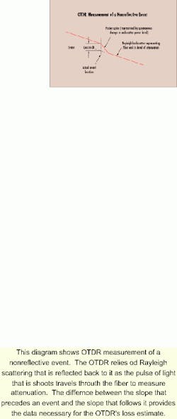
To measure fiber attenuation, the OTDR relies on Rayleigh scattering that is reflected back to it while the pulse of light that it shoots travels through the fiber. The OTDR plots a slope based on the backscatter information it measures. This measurement determines the attenuation level (power/distance) for the fiber. The difference between the slope that precedes an event and the slope that follows it provides the data necessary for the OTDR's loss estimate (see Fig. 1).
Unfortunately, the backscattering coefficient of the fiber, which may vary slightly between fibers due to changes in mode field diameters, can affect the power levels measured by the OTDR. Because the OTDR loss estimate for an event is a relative measurement that compares the backscattering power levels before and after an event, misleading information can result from comparing these power levels.
One example is a fusion splice that involves two fibers of slightly different mode field diameters. The real loss from a splice between two singlemode fibers is independent of the propagation direction of light. Yet, different loss measurements are likely to be obtained when OTDR measurements are performed from opposite ends of a fiber span. A good analogy is water going through a pipe, then down through a funnel and into a smaller pipe. Looking through the end of the smaller pipe is similar to using an OTDR; it is probably impossible to see the funnel or larger pipe. But there's a good chance that both the funnel and the smaller pipe are visible from the larger end. Although each side of the pipe assembly looks completely different, the actual water flow is the same in either direction.
OTDR measurement is affected by both the real splice loss and the back-scattering ratio difference between the fibers before and after the splice. Since the effect of the backscattering ratio difference is reversed when measurements are performed at the opposite ends of a fiber, the average of the two readings eliminates the impact of the backscattering coefficients.
To optimize event loss measurements on singlemode fiber, it's important to obtain a good-quality (unidirectional) acquisition before considering the bidirectional approach. Because the OTDR can "see" the end of a fiber, it is often assumed that every event throughout the fiber span is properly characterized and measured. In many cases, this assumption couldn't be further from the truth. The quality of event detection and measurement is highly dependent upon signal-to-noise ratio. When an acquisition becomes noisy-due to insufficient averaging time, inappropriate test settings, or poor instrument performance-the OTDR analysis software has trouble accurately measuring losses or, for that matter, locating events.
With good quality (unidirectional) acquisitions, it's possible to increase the measurement accuracy for event loss through bidirectional OTDR testing by averaging the results for each event. This method eliminates the misleading results common with mode field diameter mismatch and other phenomena.
Gainer elimination
Another instance in which different fiber-to-fiber characteristics give misleading or distorted results is the gainer event. The gainer, or positive event, shows an increase in relative backscatter at a particular splice junction.
A splice does not amplify the light that goes through it. Instead, because the properties of the two fibers are so different, the second fiber causes a significant increase in the level of backscattering-so much so that it actually exceeds the event loss. Therefore, the OTDR measures more backscattering power after the event than before it.
That clearly demonstrates the limitations associated with unidirectional testing. Contrary to popular belief, this occurrence is not limited to gainers; it can apply to any fiber-to-fiber event loss measurement. The gainer is simply an occurrence in which the phenomenon becomes obvious.
When performing an OTDR acquisition from the opposite direction, the gainer will turn into a negative event, revealing an exaggerated loss reading. Averaging the two results thereafter provides an accurate loss measurement.
0-dB event detection
When fibers with moderately different refraction characteristics are spliced, the effects of distortion can reach the mid-point range, at which an OTDR reading would show neither a loss nor a gain. In this case, the Rayleigh backscatter increases as the light crosses from one fiber to the next, although just enough to counterbalance the actual loss at the splice location.
Consequently, the net backscatter level does not change. In this case, the OTDR will neither detect the event nor indicate any associated loss. However, bidirectional testing and averaging will detect the event as well as provide an accurate loss measurement.
The main tradeoff in OTDR testing is range versus resolution. Longer links require the injection of more energy to reach the end of the fiber to characterize the complete fiber span. More energy translates into longer pulses, which in turn means longer dead zones. The dead zone is arguably the OTDR tester's worst enemy, as it can hide major reflective and nonreflective events on a fiber link.
Because dead zones occur only as a result of reflective events, bidirectional OTDR testing can help reduce the effects of the range versus resolution tradeoff significantly. Consider the case of a fiber link consisting of four sections of fiber. The first fiber section is connected to the second through a connector pair. The second to third and third to fourth fiber sections closely follow and are fusion-spliced. The dead zone caused by the first connector's Fresnel reflection may prevent the OTDR from detecting the following nonreflective fusion splice (and possibly the one after that). An OTDR test from the opposite end of the fiber link, however, would reveal all three events at each connection point because the connector-pair dead zone has no impact on the nonreflective events that precede it.
Longer distance rangeAlong with meeting the requirements for more-precise loss measurements, bi directional testing and averaging is well-suited to long-haul applications. Underwater fiber-optic-cable installation, for example, is usually very long and requires exceptionally powerful OTDRs with very high dynamic-range performance. Even the most powerful OTDRs available on the market today do not have the dynamic range needed to reach distances beyond 250 or 300 km.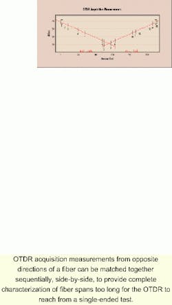
Bidirectional analysis software is helpful in characterizing fiber spans beyond the test equipment's range. Using analysis software, it is possible to add the end-to-end length of two opposite-direction OTDR acquisitions. For example, 150-km OTDR acquisitions can be taken from each end, A and B, of a 275-km fiber link. The matching events from the two opposite-direction OTDR acquisitions are aligned to create a full-length characterization of the fiber span. The result is an event table where all the events, from one end of the fiber link to the other, are numbered sequentially (see Fig. 2). The A-to-B acquisition provides the first events, followed by some combined bidirectional events, in turn followed by the B-to-A events. Because most of the events register on only one of the unidirectional measurements, they cannot all be averaged. But it is possible to document and store acquisitions for fiber spans in excess of 300 km long with some degree of accuracy.
Technology is here
The technology level of today's OTDR test equipment and software enables users to perform bidirectional OTDR analysis effectively. In many circumstances, OTDR testing at both ends of a fiber is justified.
Bidirectional OTDR testing is of great value to users who must commission and document fiber-optic links extensively. It also benefits those who are becoming increasingly sensitive to their cable-plant loss budgets. In some cases, the procedure can prove very useful in long-haul applications as well. As the demand for bidirectional OTDR testing increases, fiber operators and testers should carefully weigh its rewards.
Bruce Galbraith is outside-plant product manager at EXFO Electro-Optical Engineering Inc. (Vanier, QC, Canada).