Upstream lasers key to interactive future
Upstream lasers key to interactive future
Donald T. Gall, Mitch Shapiro
With plans to deliver a range of interactive services on their new hybrid fiber/coaxial-cable networks, cable-TV operators have been working hard to master the art of two-way network design and operation.
While the forward-path portion of a hybrid fiber/coaxial-cable (hfc) network has physical and technical characteristics that are very predictable and well understood, the reverse-path environment is considerably more hostile and less understood. This has prompted some industry critics to claim that return-path problems will ultimately kill cable`s two-way aspirations. While such critics can rightly point to some very real challenges tied to the return path, experience thus far suggests that two-way operation can be managed successfully with good design and network operations.
A key piece of the return-path equation is the upstream transmitter. In this month`s column we look at the environment in which these devices operate as well as the capabilities of the different types of return lasers now available or under development.
A one-way heritage
Traditionally, the return path in a cable- television network was not activated. If it was activated, it was in most instances neglected. The few systems that did use the return path used less that 1% of its potential capacity. The typical signal carried on this path was used for communicating with addressable cable converters. In most cases the converters used a robust, low-speed, frequency-shift-keyed data carrier running at 9.6 to 14.4 kbits/sec. The single carrier was narrow enough to be placed anywhere there was a quiet spot in the return band spectrum.
Emerging services such as virtual shopping, video-on-demand, video telephony, and high-speed Internet access will dramatically change the amount and types of data carried on the return path. Many cable operators upgrading their networks are planning to use as many as 28 1.544-Mbit/sec quadrature phase-shift keyed (qpsk) carriers in the return path, virtually filling every usable space. Some are considering using even higher-order modulation formats than qpsk in certain situations. The bottom line is that the overall reliability of the network must improve dramatically to support a much heavier use of the return path.
As alluded to earlier, the impairments found in the return path are far from benign. The following list covers the majority of impairments that affect system performance:
System noise funneling: In an analog
network the actual system noise increases by a logarithmic function of the number of devices in cascade. In the reverse, all of the sources and active amplifiers are on a parallel bus, so it follows that all of the devices are physically parallel to each other. They all add noise to the system at a rate of 10 log (N), where N is the number of active devices.
Common path distortions: Since both
the forward and reverse paths in the network are present on the same coaxial cable, any fault such as a corroded connector can cause a form of crosstalk called common path distortion (cpd). This distortion shows up as additional RF carriers. This defect will add unwanted RF power to the network as well as transmission impairments.
Second- and third-order distortions: In
any analog circuit that has more than one signal, the signals will mix at some level, depending on the linearity of the circuit. This form of distortion is very predictable and can be allowed for in the network design.
Ingress: The in-
trusion of unwanted RF signals and noise into the coaxial-cable distribution system is called ingress. The interference arises from a number of sources: wireless transmissions from amateur and CB radio, overseas radio broadcasts, hum and corona discharge from power distribution systems, and electrical noise from any source of electrical switch or motor. Ingress may be conducted into the coaxial system whenever there is a breach in the RF shielding, such as loose, corroded, or faulty connectors; damaged cable; or poor-quality drop passives. The service provider can mitigate ingress in the outside plant by proper design and maintenance of the cabling plant. Ingress is one of the major variables in operating an hfc return network. Even in a well-maintained system the RF power associated with this impairment can significantly change the amount of RF power that is given to the return laser transmitter.
Good news and bad news
As with any network solution, the weakest link often dictates overall system performance. In the return path of an hfc network, the return laser transmitter has that dubious distinction. This is true for all laser diode sources. The good news is that in a well-designed and -maintained network the actual performance needed is well within the operating parameters of the laser diodes available today. There is, however, enough difference in the range of performance and price of the various choices that the determination of which laser transmitter technology to choose is not clear-cut.
A laser transmitter in a "node" environment may be subjected to temperature extremes from -40 to +60C. All laser diodes exhibit a drop in slope efficiency at the higher temperatures in this range, causing a reduction in optical modulation index for a fixed input signal. Unfortunately, the RF levels in the coaxial plant also decrease, compounding the problem. At the cold end of the temperature range the RF levels increase, which must also be taken into account.
One method of stabilizing the laser diode might be to incorporate a thermal electric cooler (tec) unit into the laser design. In the forward path the laser performance required to handle the large analog bandwidth mandates controlling the laser temperature. The return-path lasers have less stringent analog linearity and noise requirements, and the tec module requires a large amount of electrical current, which would create the need for a larger power supply and better heat dissipation in the node. The tec does not have the range to cover the temperature extremes necessary for the application. Historically, uncooled laser diodes have demonstrated adequate performance for return-path applications.
The biggest issue surrounding the return transmitter is its dynamic range. Besides having to operate over a very large temperature range, it has to operate over a wide range of RF input power. The catch here is that the actual range of RF power is not well defined. The return sources are bursty in nature, the actual number of sources and RF carriers that will be required in the near future are only estimates, and ingress from outside sources may have as much actual power as the desired signals--or even more.
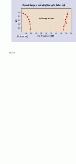
In this application, dynamic range is defined as the RF input power range within which the network delivers the proper quality of service. In some cases this is defined as the signal-to-noise ratio with acceptable distortion performance. In the future the dynamic range will be based on the performance of data carriers across the operating range. This could be accomplished by plotting the RF input power versus the bit-error rate (ber) of the carrier under test. Early estimates suggest that the RF input power should have a minimum range of 30 dB at more than 10-6 ber (see figure).
Return-path options available today include several variations of distributed- feedback (dfb) and Fabry-Perot (FP) laser diodes. Since using tec technology is not feasible for this application (unless a considerably more efficient solution becomes available), the possible combinations include using the diodes unaided, with additional isolation, or with pre-distortion added.
Laser performance has historically been based on carrier-to-noise and second order distortions of two to four unmodulated carriers and performance related to a single operating point. The cable industry has not had a unified set of performance requirements, mostly because the new services that will be carried by the network are still undergoing rapid changes.
Price/performance tradeoffs
The least expensive return laser option is an unisolated FP diode. The question remains, however, whether such devices can achieve the necessary dynamic range in a loaded environment using digitally modulated carriers. This potential problem can be minimized by using a good isolated FP laser diode or an unisolated dfb diode, both of which are likely to provide roughly equivalent performance.
However, the cost of an isolated FP diode or an unisolated dfb diode can be up to four times as much as that of an unisolated FP diode (typically $400 versus $100), resulting in transmitter prices as much as three times that of an unisolated FP ($1500 versus $500).
Thanks to improved yields, higher volumes, and aggressive pricing, dfb lasers have seen cost reductions of approximately 50% during the past few years. A definitive answer has yet to emerge, however, as to whether a dfb`s performance benefits are necessary to support current and planned applications, in light of the still-significant extra cost involved.
Actual applications bear out this point. While tci is deploying upstream dfbs in the bulk of its hfc projects, Time Warner, Cox, and others are using FPs. In large measure, these choices reflect the different approaches these companies are taking to their overall network design. While the latter two multiple system operators are investing more on the RF portion of their plants, tci is choosing to spend less on upgrading its coaxial-cable plant and, instead, is investing some of the associated savings in the additional headroom provided in the optical-fiber plant by dfbs.
Efforts are also under way to improve the dynamic range of FP devices by adding an inexpensive predistortion circuit and/or forcing isolation with an optical pad.
As new generations of interactive digital applications evolve, so too will the return-laser transmitters used to support them. Understanding the environment in which these devices will operate is key to designing a reliable, cost-effective "information superhighway." uThe future should see dynamic range measurements based on the performance of data carriers across the operating range. This range will be defined by plotting the RF input power versus the bit-error rate of the carrier under test. Early estimates suggest that the RF input power should have a minimum range of 30 dB of at more than 10-6 ber.

