New components enable management functions in the optical network
New components enable management functions in the optical network
Fully transparent networks are not yet economically feasible. However, the components necessary for such networks are starting to appear.
Andrew Schmitt, Vitesse Semiconductor Corp.
The bandwidth needs of both interexchange carriers (ixcs) and local-exchange carriers (lec) are expanding rapidly, complicating the challenge of forecasting future requirements for capacity. Network planning, especially in metropolitan environments, is becoming difficult as customers seek to transport new protocols and various Synchronous Optical Network (sonet) rates across their fiber. Existing wavelength-division multiplexing (wdm) solutions typically focus on providing a transparent and rate-independent "bit-pipe" or transporting many homogenous sonet signals. Such solutions are useful in one network-planning situation or another, but more flexibility is needed to construct a network that can react to the bandwidth demands of customers.
wdm equipment capable of appearing transparent while providing retiming and management support for multiple sonet frequencies would be a good solution. Hardware complexity previously made such architectures uneconomical. But new electrical components enable architectures with these features while providing the performance, cost, and area requirements necessary for a competitive equipment product.
The challenge of network flexibility
A transparent optical network would allow an optical signal to travel through the network without conversion to the electrical domain. Such a network would provide improved reliability, since it would eliminate the weak link of today`s network, the optical/electrical conversion. Flexibility also would be provided, since the equipment on either end of the fiber would govern the data rate being transferred, not the optical components in between. A link could be upgraded from OC-3 (155 Mbits/sec) to OC-48 (2.5 Gbits/sec) by replacing the equipment on either side of the fiber, without having to upgrade optical components in between. The optical equipment would not care about rate or protocol when transmitting data--unlike today`s network where regeneration points require the proper electrical components that conform to the data rate being transferred.
Unfortunately, optical technology to provide the cost or performance necessary for a completely transparent optical network is currently not available. Even if it were, network management would still be a problem. Transparent optical networking components would not be able to easily provide the necessary sonet operations, administration, management, and provisioning (oam&p) functions that the ixcs and lecs require. Therefore, the challenge presented to optical equipment vendors is to provide systems with the network-management features of the sonet network and the flexibility benefits of the optical network.
The majority of wdm equipment deployed today in carrier networks transports sonet in a point-to-point configuration. The sonet ring architecture is being implemented at the layer above the optical layer using existing terminal multiplexers and add/drop multiplexers, because the oam&p intelligence required to implement ring structures does not yet exist in most wdm equipment. Optical equipment vendors are seeking to add sonet management features to their products to merge the rate-independent and transparent optical layer with the sonet protocol interface layers.
While pure optical networks are rate- and protocol-independent, sonet frequencies and protocols are strictly defined. A sonet signal is composed of frames, and each frame consists of several sts channels, typically three, 12, 48, or 192. Each of these channels is composed of 810 bytes or 6480 bits. The sonet transmission frequency is determined by the requirement that each frame be transmitted in precisely 125 microsec. As an example, an OC-3 signal has three sts channels, therefore the frame contains 19,440 bits that must be transmitted in 125 microsec, resulting in a line rate of 155.52 Mbits/sec.
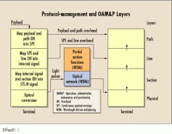
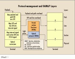
Protocol-management and oam&p functions are assigned hierarchically to three network layers: path, line, and section (see Fig. 1). The sonet path interface layer defines how the payload itself can be assembled, and has little to do with transmission. The lower protocol levels provide management of the transmission interface and are the levels that the optical layer will need to recognize and act upon to provide oam&p feedback.
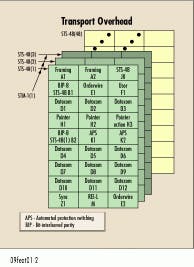
The line interface layer defines the logical point-to-point relationship between two terminal multiplexers. Here, the OC-N signal payload is assembled from other sonet tributaries or aggregated from a single source in the case of concatenated sonet (OC-Nc). This payload is wrapped with additional bytes called the transport overhead, representing 27 of the 810 bytes (see Fig. 2). These additional bytes provide the means for implementing most of the sonet oam&p functions for framing, bit-error rate, datacommunications, network protection status, craft communication, and resolving system clock mismatches between terminal equipment.
The section interface layer is a subset of the line, representing the division of the logical line connection into one or several physical segments. A section is typically an electrical regenerator that re-times the sonet signal, performs housekeeping functions that check signal integrity from a physical and logical standpoint, and provides craft and data communications. These functions are carried out by 9 of the 27 bytes in the transport overhead, specifically the first three rows in Figure 2.
The sonet physical layer is the physical medium and the optoelectronic device responsible for actual transport of digital data from the section layer. Transparent or retiming wdm equipment without the ability to inspect the sonet signal would sit in between the existing physical interfaces of sonet equipment.
We can extend the wdm layer to occupy a portion of the logical sonet layers if the equipment`s electrical components have the ability to observe and act upon the bytes contained within the transport overhead shown in Figure 2. Bytes A1 and A2 are set to F6H and 28H for all N channels in the sts-N, providing a byte boundary that is used for byte alignment. Detecting the periodic or constant loss of this periodic boundary is a vital part of sonet fault tolerance. The B1 byte represents even parity of all of the bytes in the previous frame, allowing for bit-error-rate calculations down to 10-5 accuracy to provide historical performance data that would highlight reliability problems on a particular section. Visibility of the J0 section trace byte allows the wdm system to verify the proper provisioning of the network. The J0 identifier marks a signal allowing electrical and manual connections to be verified in software. K1 and K2 designate the protection status of the transported signal and give the wdm network the ability to act on that data.
The equipment should be able to perform these functions at multiple sonet rates and be provisionally transparent for accommodating non-sonet traffic. Finally, the architecture should be flexible enough that adding more oam&p features, such as modification of the dcc bytes (D1, D2, and D3), should not require a major hardware change.
Hardware oam&p solution
Existing electrical components do not allow the realization of such a system without significantly increasing the hardware complexity of the system. Adding in the ability to support transparency increases complexity even further. These functions scale linearly with the number of channels provisioned in the chassis. As a result, the design is especially cost-, power-, and footprint-sensitive. A new architecture enabled by electrical components suited specifically to this task is needed to economically provide sonet management features as well as the transparency associated with traditional optical networks.
The conventional architecture for observing the transport overhead would use a tuned OC-48 clock and data recovery (cdr) unit driving a discrete 2.488-GHz demultiplexer with a loopback output, which would then feed an application-specific integrated circuit (ASIC) through a 16- or 8-bit bus. No means for achieving transparency exist, and a custom ASIC development will be necessary. If additional features were to be included in the future, this ASIC would have to be redesigned. If future plans were to require modification of the transport overhead, this architecture would have to be heavily modified to include a multiplexer and clock distribution.
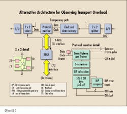
An alternate architecture is shown in figure 3. The goal is to keep the OC-48 data stream serial, allowing asynchronous switching to take place for transparency, as well as minimizing the number of board traces. The key element of this approach is a device that has an interface capable of speeds up to 2.488 Gbits/sec and internal logic for performance monitoring of the sonet signal. All high-speed operations are isolated within this device, which allows the oam&p logic to be included alongside in a slow field-programmable gate array (fpga). Also needed is a 2 x 2 crosspoint that provides a frequency-independent transparency path around the cdr unit. It is important that both devices use cmos-type (+3.3V) power supplies to eliminate the need for additional power rails, which would add cost.
The monitoring device receives clock and data from the cdr unit at rates up to 2.488 Gbits/sec and provides a retimed output that is used for retransmission. Byte alignment is performed using sonet-compliant framing algorithms. Severely errored-frame and loss-of-frame alarms need to be provided as well. Once byte alignment is completed, the part can de-scramble the signal and utilize the sonet B1 byte to perform bit-error-rate calculation. All 27 bytes of the transport overhead are output as well, providing visibility to K1/K2 for protection status and visibility of the J0 section trace byte for provisioning verification. Framing and overhead output features function at the popular sonet frequencies: OC-3, OC-12 (622 Mbits/sec), and OC-48.
Except for the high-speed 2.488-Gbit/sec clock and data inputs, as well as the retimed output, the device`s I/Os are ttl operating at single-megahertz frequencies. This setup allows the system designer to implement custom oam&p processing by using inexpensive fpgas or programmable logic devices instead of high-frequency asics. Integration of the 2.5-GHz retiming interface, 2.5-GHz demultiplexer, and several thousand gates of logic allows processing of the sonet signal at a byte level (311 Mbits/sec) and reduces the logic density significantly.
A 2 ¥ 2 crosspoint performs the 1:2 signal splitting and 2:1 signal selecting necessary for the transparent bypass. The select input should be ttl-compatible to receive provisioning commands from the fpga. This function is logically simple, and devices are available in the general market that meet the necessary 2.488-Gbit/sec data rate and 3.3V supply requirements.
Future enhancements
The use of the fpga for implementing the oam&p features gives this architecture the flexibility to add more capabilities once the suporting network software is capable of using them. Another possibility would include upgrading the existing monitor device to provide recognition of 8B/10B encoding, allowing for a crude but effective means of validating Gigabit Ethernet, Fibre Channel, and Escon protocols.
The retiming interface of the monitor could be replaced with a part that integrates both a demultiplexer and a multiplexer. Additional logic can be included between these that would enable modification of the J0 and D1, D2, D3 bytes, allowing the device to assume more section-termination capabilities. Implementing these changes would involve replacing the monitor chip with a modifying device, but the serial architecture of the system would remain unchanged.
Inclusion of the ability to write the section overhead allows the optical network to assume the abilities of the sonet section layer. Typically, an out-of-band optical communication channel is used for wdm devices to communicate with each other. Giving nodes the ability to read and write the data-communications channel bytes would eliminate this out-of-band channel and reduce system cost. Allowing the optical network to read and write to the J0 byte would allow its use within the network for its intended purpose, the checking of network interconnect provisioning.
However, once optical networking equipment vendors start modifying J0 and the data-communications channel bytes or implementing protection schemes, they will no longer be transparent to the surrounding network. This lack of transparency will force them to guarantee management software interoperability between existing sonet equipment and their optical network, a challenge far more formidable than the hardware challenges involved in creating a flexible optical networking architecture.
Toward flexible wdm networks
Ultimately, customers want the optical network to be transparent, with no electrical components in the networking path. Network functions such as wavelength add/drop and crossconnects would be done optically in this environment. But wdm equipment, optical add/drop multiplexers, and optical crossconnects may not be generally accepted into the public network until they can accommodate the network-management features expected by the ixcs and lecs.
New electrical components need to be specifically designed for the needs of optical networking equipment. These components should provide sonet oam&p functionality and multiple-rate support in a small, power-efficient footprint, allowing optical networking-equipment manufacturers to provide the functionality and flexibility required by their customers. These components would enable transparency, allowing the optical network to transmit sonet, as well as non-sonet data using an asynchronous bypass of clock recovery units. Furthermore, the architecture should be easily upgradable so more sonet oam&p and even non-sonet functionality could be incorporated within the equipment.
While truly transparent optical networks may not be a reality today, the components are available that allow construction of an optical network capable of managing sonet traffic or acting transparently. This ability will allow wdm to fulfill the needs of existing sonet customers while providing the capability for non-sonet traffic. u
Acknowledgements
The author would like to credit Richard Kerdock, Bill Woodruff, and Gregg Borodaty for their contributions to this article and the architecture discussed.
Andrew Schmitt is a telecommunications application engineer at Vitesse Semiconductor Corp. (Camarillo, CA).Fig. 3. The key element of this alternative approach is a device that has an interface capable of speeds up to 2.488 Gbits/sec and internal logic for performance monitoring of the sonet signal.


