Evolution toward 50-msec shared mesh rerouting in AONs
Traditional carrier optical networks are built around SONET/SDH equipment using interconnected ring topologies with 50-msec traffic restoration in an equipment failure or fiber cut. However, ring-network topologies have two major drawbacks. First, adding incremental bandwidth as the network grows or traffic patterns change is challenging and expensive. All interfaces on nodes in an interconnected ring need to be updated to the same speed at the same time, so upgrade costs are high. Second, the 50-msec restoration guarantee requires network over-provisioning by at least 100%. In an interconnected ring, traffic flows along two paths where the destination node can select the "better" path—a network configuration commonly known as 1+1 SONET protection.
An alternate optical mesh architecture using point-to-point links can achieve the 50-msec guaranteed protection while reducing capital and operating costs. An optical mesh network consists of optical transport nodes interconnected by point-to-point links in whatever configuration carriers deem appropriate; the network topology is no longer constrained to interconnected rings. This configuration addresses the first limitation of interconnected rings by allowing an increase in bandwidth via additional point-to-point links and optical transport nodes. It's no longer necessary to upgrade all nodes to increase bandwidth between any two endpoints.
A primary enabler of optical mesh-network deployment is the development of the Generalized Multiprotocol Label Switching (GMPLS) protocol. GMPLS is a fundamental step in the evolution and integration of data and optical networks, because it enables control of heterogeneous technologies using one set of protocols.
Router and optical equipment vendors are co-developing this standardized protocol to enable the service layer to dynamically request bandwidth from the transport layer. GMPLS is an extension of the MPLS control plane, adapting its signaling and routing protocols for use with optical switches, in addition to the routers and ATM switches that MPLS already supports. Enhancements to existing MPLS protocols required to address optical-network characteristics include:
- Resource reservation protocol-traffic engineering (RSVP-TE) enhancements to allow signaling and instantiation of optical-channel trails in optical transport networks and connection-oriented environments.
- Open shortest path first (OSPF) and intermediate system–intermediate system (IS-IS) interior gateway routing protocol (IGP) enhancements to advertise optical resource availability, other network attributes, and constraints.
- A new link management protocol (LMP) to address link management-related issues in optical networks.
Additional GMPLS functionality addresses MPLS control-plane limitations such as the inability to establish a bidirectional label-switched path (LSP) in one signaling request, the absence of mechanisms to account for protection bandwidth to be used for lower-priority traffic, link protection attributes, and the ability to signal out of band with respect to user data.
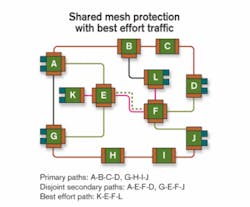
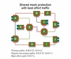
Shared mesh restoration uses the GMPLS control plane to establish a primary optical-channel trail, instantiated as an LSP between a pair of endpoints in the optical mesh. This primary LSP carries user data between the two endpoints. To protect the primary LSP, a second independent LSP is established between the same two endpoints. Unlike the primary LSP, no resources (e.g., wavelengths or timeslots) are allocated to the secondary LSP in the links and nodes along its path. If network failure occurs anywhere along the primary LSP, its protecting secondary LSP is activated—a signaling request converts it into the primary LSP. Resources along its path are allocated, and user data is carried over it.
Optimized for a single network failure, this implementation allows two or more secondary LSPs to share resources in the optical mesh network if the primary LSPs they protect are disjointed. This capability addresses the second limitation of interconnected rings by allowing shared restoration resources. It also enables lower-priority, best effort, primary LSPs to use restoration resources to carry user data until network failure claims those resources.
Hardware-based SONET/SDH network restoration involves four steps: isolation, localization, notification, and mitigation. In control-plane-based optical networks where messages are exchanged between nodes, these four steps would not allow the 50-msec restoration that carriers expect. However, a shared mesh restoration implementation can leverage photonic-switch transparency to remove isolation and localization from the critical path for restoration. It accelerates notification and mitigation as follows:
- With primary and secondary LSPs on different paths through the optical mesh, network failure anywhere along the primary LSP causes activation of its protecting secondary LSP. Thus, the isolation and localization steps need not be on the critical path for restoration.
- Since the data plane in a photonically switched network requires no optical-to-electrical conversion at intermediate nodes, network failure is detected in the nodes containing the primary LSP endpoints at the speed of light in the time needed for the loss of light event to propagate to those nodes. Thus, the notification step is performed end-to-end in the data plane at the speed of light.
- Activation of a secondary LSP for fault mitigation requires an RSVP signaling message from the ingress to the egress node, hop by hop along the LSP, followed by another RSVP signaling message from the egress to ingress node, again hop by hop. Thus, all nodes along the path have correctly established the data plane for the LSP, ensuring user data will not be misdirected.
- Another approach, just in time signaling, establishes the data path between the ingress and egress node with a single RSVP signaling message sent hop by hop from ingress to egress node. While this message is in transit, user data may be misdirected, but all user data is tagged with unique per-LSP identifiers. Nodes receiving misdirected user data, simply discard it.
These two nodes use GMPLS signaling, specifically RSVP-TE ("PATH" and "RESV" messages), to establish primary and secondary paths. A bit in the PATH message, sent from originating to terminating node, indicates whether the path being established is a primary or secondary path. If the path being established is primary, each node along the path (originating, intermediate, and terminating node) programs its switch matrix to allocate the path in both forward and reverse directions. If a best effort path is using resources needed to allocate the path, it is preempted. If the path being established is a secondary path, nodes along the path do not allocate resources at this time. Instead, those nodes reserve the requested resources, allowing them to be used by other best effort paths until the originating node reclaims the resources by sending a subsequent PATH message indicating the path is now a primary. That is known as activating a secondary path.
To allow intermediate nodes to share protection resources, the route taken by the primary path is carried in the PATH message used to establish the associated secondary path. An intermediate node compares the route taken by the primary path with routes of other primary paths whose secondary paths use the same resources as the secondary path being established. If primary paths have no elements in common, protection resources may be shared. In a single network failure, all affected primary paths can then activate associated secondary paths without protection resource contention.
An ITU-standard G.709 or a SONET/SDH transponder pair at either end of every primary/secondary-path pair monitors for loss of light (LoL) on bidirectional fiber failure and either backward defect indication (BDI) for G.709 or remote defect indication (RDI) for SONET/SDH on unidirectional fiber failure. These transponders detect primary-path failure in the time needed for LoL or BDI/RDI to propagate at the speed of light to primary-path endpoints.
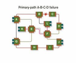
To prevent misdirected customer light when activating a secondary path, a unique network-wide value or "PATH ID" is carried in every frame's G.709 or SONET/SDH header sent over a given path. This value is exchanged by path endpoints when the path is established. If the endpoints receive a G.709 or SONET/SDH frame on a path with a value different from the one established for that path, they discard it. For a primary/secondary-path pair, the network-wide value is the same for both paths.In Figure 2, the link between nodes B and C fails, causing the G.709 or SONET/SDH transponders at either end of primary path A-B-C-D to detect failure via LoL or BDI/RDI. Primary/secondary-path pairs have no elements in common, hence when node A detects the failure of primary path A-B-C-D, it immediately begins activation of associated secondary path A-E-F-D without waiting to determine that the primary path failed due to failure of the link between B and C. Fault isolation occurs subsequently, using GMPLS LMP fault isolation procedures. Thus, once the "good" segments of the links are rechecked using LMP verification procedures (i.e., segments A-B and B-C), they are declared operational and flooded back into the IGP database. This operation does not slow the mitigation process.
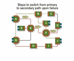
To switch from the primary path to the secondary path in the event of failure, node A sends a PATH message indicating that path A-E-F-D is now primary, which is forwarded by nodes E and F, eventually reaching node D (see Figure 3). Each node in parallel programs its switch matrix to establish the path in both forward and reverse directions. Nodes E and F also preempt best effort path K-E-F-L and notify nodes G and J that secondary path G-E-F-J no longer has segment E-F.During the entire protection-switching period, G.709 or SONET/SDH transponders do not turn off. The instant that all four nodes along the path have processed the PATH message and programmed their switch matrices, the path between A and D is restored and transponders are reconnected.
To reduce control-plane overhead, multiple secondary paths sharing the same route are activated with one GMPLS PATH message. Which secondary paths share which routes is identified during failure analysis at the originating node.
In today's networks, SONET/SDH provides independent working and protect paths. To provision N, such connections need (N*H + N*H*a) resources, where H is the average set of resources used for primary-path build-out and H*a the average set of resources used for secondary-path build-out. Typically, a is in the 1.2–1.8 range and dependent on secondary-path length, the traffic matrix, etc.
In shared mesh architectures, it is possible to do a similar ring build-out and use (N*H + N*H*a) resources. The proposed solution for point-to-point shared mesh optical nodes enables reuse of secondary-path segments for numerous connections. Thus, the resources needed are (N*H + N*H*b), where the first term corresponds to resources needed for primary path and the second term corresponds to resources needed for secondary path; typically b is in the 0.6–0.8 range in simulations, implying over 50% savings in the protection resources for point-to-point shared mesh architecture versus traditional interconnected ring builds. Since both architectures provide 50-msec restoration guarantees, the lower-cost build with point-to-point optical-node network layout is not far in the future.
John Drake is chief network architect and Ayan Banerjee is a systems engineer at Calient Networks (San Jose, CA).


