Assure measure for measure with reference-quality test cables

Standards bodies are finally identifying precise requirements for reference components.
DENNIS HORWITZ, RIFOCS Corp.
Let's set the record straight. Most measurement problems are not caused by faulty test equipment, but they can result from the quality of the interconnections used in the test setup. While routine cleaning and inspection of the test setup are obvious requirements, the need to use test-grade, reference-quality cables for all connections is less understood.
Network equipment and cabling must meet specifications in order for systems to function properly. Standards help ensure that products perform as advertised. If equipment meets industry standards, then end customers can verify or reproduce the measurements performed by manufacturers and contractors. Without standards, the potential for disagreement and dispute exists. In extreme cases, the customer and supplier end up in court.
In North America, the communications industry adopts the fiber-optic standards developed by the FO2/FO6 fiber-optic committees and TR42 premises cabling group under the auspices of the ANSI-accredited Telecommunications Industry Association (TIA, http://www.tiaonline.org/standards/sfg/): fiber-optic test procedures (FOTPs) for component-level testing or optical-fiber system test procedures (OFSTPs) for systems-based testing. For the purposes of this article, specific test methods will be referenced by their generic designations, i.e., FOTP-XXX (referring to the TIA/EIA-455-XXX series of standards documents) or OFSTP-XXX (referring to the TIA/EIA-526-XXX). The fiber-optic connector intermateability standard (FOCIS) documents, which cover specific connector designs-FOCIS-2 for the Bayonet or ST, FOCIS-3 for the SC, FOCIS-4 for the FC-are available under the TIA/EIA-604-XXX series.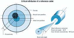
Other highly regarded standards organizations include Telcordia Technologies (http://www.telcordia.com/) and the International Electro technical Commission (IEC, http://www.iec.ch/). Telcordia is responsible for establishing the performance, interoperability, and quality requirements for components, systems, and processes for use in the telecommunications industry, much like its predecessor Bell Com munications Research, the standards and engineering arm of the regional Bell operating companies. (Telcordia's GR-326 CORE standard is widely used to establish performance requirements of singlemode connectors and cable assemblies.) The IEC is an internationally recognized standards body, especially outside of North America.
The IEC and TIA often create different standards for a given process or product. However, the globalization of the market is driving the development of a single, international set of standards. The IEC 61300-XX-XX series of standards are largely equivalent to the TIA's FOTPs and OFSTPs. (All TIA, IEC, and Telcordia standards documents can be purchased online from Global Engineering Documents at http://www.global.his.com/.)
Successful testing requires more than adherence to standard test methods, however. Technicians must use quality, calibrated, and properly maintained test equipment as designated by the test method and reference-quality test cables for all connections. Finally, personnel must be trained in the proper test methodology and set up.
A reference cable is not a random cable pulled out of a box of patch cords. By definition, a reference cable is a complete fiber-optic cable assembly with fiber-optic connectors precision-mounted on each end, accompanied by the appropriate documentation certifying its "Reference" pedigree. These devices are also known as reference launch cables, golden cables, test jumpers, and measurement-quality jumpers (a U.S. Navy designation per MIL-STD-2042). Reference cables are used because they provide a repeatable reference point for measurements such as cable assembly attenuation or return loss. Reference components (cable assemblies and mating adapters) are distinguished from standard "field-grade" components by their low loss when mated together, regardless of rotational orientation. This low loss indicates that the cores of the fibers in the reference connectors are highly concentric relative to the outside of the ferrules and that the beam exit angle/cone (also know as the radiation angle or skewing) is aligned axially with the ferrule (see Figure 1). Reference adapters are capable of aligning the cores consistently and precisely.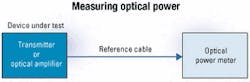
For years, FOTPs and OFSTPs have been notoriously weak in describing precise requirements for reference components. The newly released revision A of FOTP-171 (TIA/EIA-455-171A, June 2001, Attenuation by Substitution Measurements for Short-Length Multimode Graded-Index and Single Mode Optical Fiber Cable Assemblies) provides the most useful descriptions and default values for reference cables in Annex A, "Selection and Qualification of Reference Components." Tables A1 and A2 of FOTP-171A provide the critical parameters and default values applicable to the most popular 2.5-mm and 1.25-mm cylindrical ferrules and physical contact connectors. As alternate ferrule technology connectors such as MT-RJ and MTP ribbon connectors emerge, the standards committee will incorporate this information into revisions of the document.
A singlemode FC or SC reference connector must meet the following criteria:
- Ferrule outside diameter: 2.4990 ±0.0005 mm.
- Polished endface geometry: per Telcordia GR-326-CORE.
- Polished ferrule length: per applicable FOCIS document.
- Reference connector attenuation: <0.15 dB at 1,310 nm and 1,550 nm.
- Beam exit angle: <0.25 degree.
- Eccentricity: <0.25 µm.
While return loss is not specified because FOTP-171 is only for measuring attenuation, a minimum return loss that is at least 10 dB better than the minimum acceptance value is recommended.
The most fundamental measurement in fiber optics is optical power (see Figure 2). How much power does the transmitter output? How much power is at the output of the optical amplifier or pump laser? How much power is available at the input of the receiver? As networks adopt gigabit data rates and DWDM transmission technology, customers are paying a pretty penny for output power and DWDM-compatible precision wavelengths. And they want to get every dB that they paid for. Use of a standard test procedure and reference cables is critical to meeting these needs.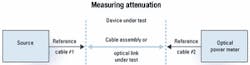
While many people view the measurement of optical power as an obvious exercise, a lot can go wrong. It involves more than just hooking up an optical power meter (OPM) to the optical output. For guidance, users should refer to FOTP-95 (available as TIA/EIA-455-95), which highlights the nuances in performing correct optical power measurements. On the assumption that the power meter selected is properly suited to the measurement (proper wavelength sensitivity, measurement range, and National Institute of Standards and Technology traceable calibration), any other variations in measured power will be due to the choice of "test" cable connecting the device under test to the OPM.
Beyond any recommendations in the product literature, the manufacturer has little control over the quality of patch cables that the end-user procures and uses for his interconnections. In order to build a quality product and ensure that the production line runs smoothly with expected yields, the manufacturer needs a repeatable baseline, which is achieved with a reference connection. Reference cables eliminate any ambiguity in the measurement process.
Attenuation, or optical power loss, is the second most common measurement in fiber optics. Attenuation (expressed in dB) is simply the ratio of optical power out to optical power in. As illustrated in Figure 3, the most common attenuation measurements performed are those of cable assemblies/patch cords or the end-to-end loss of an installed fiber-optic link. The following list indicates the applicable standards:
- Attenuation of cable assemblies: FOTP-171 (available as TIA/EIA-455-171A).
- End-to-end loss of singlemode links: OFSTP-7 (available as TIA/EIA-526-7).
- End-to-end loss of multimode optical links: OFSTP-14 (available as TIA/EIA-526-14).
- Attenuation of fiber-optic components: IEC 61300-3-4.
In applying any of these standards, the end user should be aware of two potential sources of measurement variation. First, each measurement standard offers distinct test methods and corresponding setups. The selected test method is based on the end user's requirements. Second, substituting poorly made, non-reference cable assemblies (standard patch cords) may add considerable measurement uncertainty, as much as 1-2 dB.
The TIA attenuation standards provide the best guidance on the use and attributes of reference cables. The FOTP-171A (for testing cable assemblies) provides the best definition and requirements for reference cables. In support of standardization and consistency, the OFSTPs for optical-link testing specifically cross-reference to FOTP-17A for reference cable guidance.
As networks move to gigabit data rates and DWDM broadband transmission technology, the return loss of optical components is a critical issue. Laser source stability and signal clarity are affected by light feedback from the components in the link, particularly connectors. Unlike attenuation, which measures forward optical throughput, return loss (also called reflectance) measures the ratio (in dB) of the power reflected by the port of a component or assembly to the incident power. The generic measurement setup is shown in Figure 4 for these standard return loss test methods:
- Return loss by optical continuous-wave reflectometer method: FOTP-107 (available as TIA/EIA-455-107A).
- Return loss by optical time-domain reflectometer (OTDR) method: FOTP-8 (available as TIA/EIA-455-8).
- International standard for return-loss measurements (all methods): IEC 61300-3-6.
Unlike the TIA attenuation test methods, the current versions of the various TIA or IEC documents do not provide any guidance on reference cables for measuring return loss. Until these documents can be suitably updated, the user is referred to FOTP-171A for overall characteristics and attenuation performance with the added suggestion that the return-loss performance be at least 10 dB better than the minimum acceptance value. Otherwise, the use of poor quality test cables will usually lead to inaccurate and understated return-loss values.
Reference cables are an essential part of the test. As such, these components require careful handling, use, and storage to maintain their integrity. Reference cables should be organized, labeled, and serialized and provide the same care and maintenance as test equipment. Frequent cleaning and visual inspection are essential, as these connections are exposed to the most handling, use, and potential abuse.
This cleaning and maintenance must consistently follow procedures to assure minimal degradation over multiple cleanings. Depending on the amount of use, matings with the device under test will ultimately cause some degradation of the reference cable connector's end-finish quality. When the procedural inspection indicates the necessity, a re-polishing may be done to restore the reference cable to its original condition. Of course, this re-polishing must not go beyond the specified minimum ferrule length (consult either the applicable TIA FOCIS document or manufacturer's specifications) to ensure proper engagement and physical contact of the mated ferrules. Minimum ferrule length assures adequate spring loading and positive fiber-to-fiber interfacing at all times. If the connector ferrule length falls below the minimum, the reference cable must be discarded or reworked with the installation of new connectors.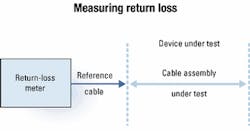
Measurement success is based as much on the quality of the reference cabling which connects the devices under test to the test setup as it is on the test instrumentation. Both are critical to assure quality test results. It is common practice to send out the instrumentation for periodic calibration. Fiber-optic reference test cables must be checked out for calibration even more frequently because of constant usage and handling. Telcordia GR-326-CORE requires the use of reference cable interconnects for no more than 1,000 matings and dematings. This specification further states that the manufacturer must have a method to determine how many times the reference parts have been used in finished goods testing. In addition, the reference cables must be frequently checked for wear. The frequency of the periodic checks for wear (loss) should be established as part of the manufacturing requirements. Mating adapters must also be periodically checked for wear and frequently inspected visually for workmanship and appearance.
Reference cables must be stored properly in a protected environment with appropriate caps or covers on the connector ends. They should be stored in a container that will assure space to keep from exceeding the minimum recommended bend radius of the cable. Care should be taken in the use of the reference cables so that these components are not kinked, twisted, or dropped during use. Protective caps should always be replaced when the cables are not in use, even when the cables are left out on the bench for testing later in the day. Reference cables will have a long service life if care is taken to maintain them properly in use and storage.
Reference cables and adapters are as important to test and measurement as the test equipment and the device under test. These components offer a repeatable reference point for measurement. Production testing runs smoother. Test time is reduced and time and money are saved. Proper use and handling of reference cables will provide consistent measurement results to both supplier and customer.
Dennis Horwitz is vice president of marketing and business development at RIFOCS Corp. (Camarillo, CA).
Lightwave is a monthly international publication focusing on fiber optics and optoelectronics, the technologies driving the growth, convergence, and improved performance of telephony, computer communications, and video. Lightwave provides technology news as well as applications and product information for corporate and technical managers and staff engineers. Lightwave's editors emphasize analysis and interpretation in their reports on the technological impact of fiber-optic components, systems, and networks in these markets.