Optimal 10-Gbit/sec interface standard simplifies component interconnect
By PRASAD SRISTI
PMC-Sierra
Internet traffic continues to increase at an incredible annual rate due to the growing number of Internet users and proliferation of bandwidth-hungry applications. As Internet traffic increases, faster links are provisioned in the core of the network, and links that were once only provisioned within the core of the network begin to proliferate out toward the edge.
Today, service providers are deploying OC-192 (10-Gbit/sec) links in the transport network, and equipment vendors are currently designing 10-Gbit/sec interfaces for deployment in the MAN. The emergence of 10-Gigabit Ethernet has given system designers yet another protocol choice at 10-Gbit/sec data rates, in addition to OC-192 packet over SONET (PoS) and ATM.
New interface requirements
The popularity of a wide variety of protocols at 10 Gbits/sec and the data rate itself present a new set of challenges in system design. It is essential for system designers to have a standard component interface that meets the demands of IP and optical-networking equipment.
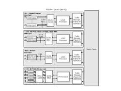
Ideally, such an interface must be able to transfer PoS, ATM cells, and 10-Gigabit Ethernet frames. The interface must also have the capability to support simultaneous transfer of multichannel OC-48 (2.5-Gbit/sec), OC-12 (622-Mbit/sec), and OC-3 (155-Mbit/sec) channelized PoS and ATM interfaces, Gigabit Ethernet, and Fast Ethernet, as required by the new generation of routers and switches for multiservice voice and data networks.
Designers of 10-Gbit/sec systems are facing increasingly tighter power budgets and board space is becoming scarcer--two issues that must be addressed. Also, a widely accepted, standardized interface is preferred, since it reduces the system design risk and improves time-to-market by enabling reuse of architectures across different line cards and systems.
PoS-PHY Level 4 system interface
The PoS-PHY Level 4 (PL4) interface continues a long history of interface specifications from the Saturn Development Group, which comprises more than 30 networking equipment companies developing and defining specifications for interoperability in next-generation network equipment. The group created the PoS-PHY Level 2 interface specification to add packet-transfer capabilities to a previous ATM cell interface for 622 Mbits/sec. The PoS-PHY Level 3 (PL3) interface was developed for packet transfers at 2.5 Gbits/sec and was standardized at the Optical Internetworking Forum (OIF) as System Packet Interface (SPI)-3.
In 2000, the OIF standardized System Packet Interface Level 4 (SPI-4) Phase 1, a 64-bit-wide packet-based interface for 10-Gbit/sec rates. Driven by the need for lower pin count and power, the Saturn group created PL4, a 16-bit-wide 10-Gbit/sec interface based on the system expertise and implementation experience gained by the architects of PL3. PL4 has since been standardized at the OIF as SPI-4 Phase 2 and at the ATM Forum as frame-based ATM Level 4 (FBATM-4).
PL4 provides an industry-accepted standard that was specifically engineered to address 10-Gbit/sec system design requirements. PL4 lowers system cost and power while increasing signal integrity, compared to earlier 10-Gbit/sec interfaces. To achieve these improvements, PL4 leverages advances in silicon technology to increase the operating speed while using low-voltage differential swing (LVDS) input/output (I/O) for greater signal integrity.
From a high level, PL4 is a 16-bit interface based on LVDS I/O, running at a minimum of 622 Mbits/sec. The PL4 interface provides in-band control and an out-of-band status channel for flow control. The status channel is implemented as a 2-bit-wide status bus that provides per-channel receiver status in a weighted round-robin fashion. The in-band control indicates channel address, start and end of packet, and checksum.
The data and the status paths are accompanied by clock signals. Source synchronous clocking is used in which the data path is clocked on both rising and falling edges of the clock signal--the data path is based on a dual-data-rate scheme. The PL4 interface protocol includes training patterns that enable the design of dynamically aligned de-skew mechanisms. More details on the PL4 specification are available at http://www.pmc-sierra.com/posphylevel4; details on the SPI-4.2 specification are at http://www.oiforum.com/.
Protocol-agnostic interface
Today's internetworking equipment must support a variety of port types, including multiple protocols and various levels of channelization, requiring a significant number of different physical layer (PHY) devices. It is a challenge for system vendors to develop a family of line cards with time-to-market and resource pressures.
Using off-the-shelf PHY devices based on a common multiprotocol interface minimizes the design resources and development time for a complete product line. Also, with the emergence of converged devices that support multiple protocols, an interface that supports simultaneous transfer of different protocols is essential. By leveraging such standards-based interfaces with strong industry support, system vendors can protect their ASIC investment by being able to connect to a broad selection of commercially available PHY devices.
PL4 supports simultaneous transfer of multiple protocols by using a simple control protocol to decouple interface operation from the actual data being transferred. PL4 uses in-band control words (payload, idle, and training control words) that are inserted between data transfers. Each PL4 data transfer is preceded by a payload control word that indicates the port address, a start-of-packet indicator, and an error control code based on diagonal interleaved parity (DIP-4).
Idle control words are transferred across the PL4 interface when there is no packet data available for transfer.A payload or idle control word that follows a data transfer also indicates the end of packet status (EOP) of the preceding transfer. Training control words are periodically transferred across the interface to allow receivers to align with the received data.
Power-efficient interface
New data rates continue to push the limits of power density in equipment boxes. At the same time, carrier equipment rooms are becoming more space-constrained while placing tighter requirements on equipment power consumption. As a result, equipment vendors are increasingly conscious of the power consumption of each and every component in their design.
Component interfaces account for a significant portion of the power within a device. By using LVDS logic I/O and being a narrower and faster interface, PL4 consumes less power than alternatives such as SPI-4 Phase 1 and Utopia 4. An added benefit of a narrower interface is the reduced board space requirements due to fewer traces being needed.
Robustness for plug-and-play
The distance traversed by a chip-to-chip 10-Gbit/sec interface depends on the equipment architecture. In cases where the PHY device and link layer device exist on the same card, such interfaces may only need to run over a few inches of printed circuit board. But as the number of required line cards increases, many box architectures are adopting a strategy where the PHY-dependent circuitry is on a separate card from the PHY-independent higher-layer packet processing devices.
In some cases, mid-plane-based architectures may require the system interfaces to support longer distances, running into tens of inches and two or more connectors. In such scenarios, the signal integrity of the interface becomes of paramount importance.
Vendors are also being challenged to find more efficient ways to develop the large variety of line cards being demanded by their customers. It is no longer cost-effective to optimize the system interface design and layout for each and every line card. Today's system interfaces should be robust and virtually plug-and-play, handling trace length differentials without imposing a heavy penalty on the board design complexity.
To support extended reach applications (i.e., over backplanes and connectors), the PL4 specification allows for the implementation of advanced receiver architectures. Such receivers use the interface training patterns for dynamic de-skew of the received data on a line-by-line basis, resulting in an interface capable of running over a meter of printed circuit board (PCB) trace material with two connectors. PL4 also can be a virtual plug-and-play interface when PL4 dynamic alignment is used, reducing board-layout effort.
Efficient multichannel operation
Today's 10-Gbit/sec interfaces need to support fat pipes of data, such as 10-Gigabit Ethernet or OC-192c PoS, as well as aggregate channels of lower-rate signals such as OC-192 channelized to STS-1 (51 Mbits/sec). To meet these requirements, PL4 has been specified to handle up to 256 logical channels, which is sufficient for OC-192 channelized down to STS-1 and 100 or more Fast Ethernet channels that compose a 10-Gbit/sec aggregate data rate. It is also important to note that in a multichannel implementation of PL4, the channels can have different bandwidth--the round-robin sequence in the status channel can be weighted accordingly.
To ensure fair operation between channels and prevent head-of-line blocking, data is segmented and sent across the interface in bursts. The specification requires these bursts to be a multiple of 16 bytes. But since the whole packet itself need not be a multiple of 16 bytes, the last of the transfer to complete a packet is exempted from this rule. To maintain bandwidth fairness across multiple channels and ensure the efficient use of receiver first-in/first-outs (FIFOs), transfers from different channels may be interleaved.
With the current state of IC technology, it may not be feasible to support packet processing functions for both transmit and receive 10-Gbit/sec data streams in a single link layer device. Hence, it is important for a system interface to support separate (unidirectional) link layer devices for transmitting and receiving data streams. By carrying the return FIFO status information out-of-band from the data path, the PL4 transmit and receive interfaces become decoupled and can operate independent of each other, thus supporting unidirectional implementations.
Broad industry adoption
Standards-based interfaces cannot achieve their goals unless they are widely adopted. Early 10-Gbit/sec interfaces caused some confusion as the ATM Forum and OIF went down divergent paths. The OIF chose HSTL [PS1]I/O (SPI-4 Phase 1) for ease of implementation in previous silicon processes where the ATM Forum went with LVDS (Utopia 4) for greater signal integrity.
But by choosing a 32-bit data path, Utopia 4 did not go far enough in reducing pin count and power or in providing a simple mechanism to support unidirectional link layer applications. As the next-generation interface, PL4 provided an excellent opportunity for alignment between the OIF and ATM Forum and was adopted at both standards groups as SPI-4 Phase 2 and FBATM-4, respectively.
The PL4 specification states a minimum operating frequency of 622 MHz per bit to accommodate the payload of an OC-192c PoS data stream plus the overhead added by the PL4 protocol. To support multiple network applications, the maximum frequency of operation was not specified by the PL4 standard.
Using currently available technology, the LVDS signaling can reach well over 800 MHz of operation. However, 700 MHz gives more than sufficient headroom required for PHY to link layer interfaces with up to 16 channels. The ability to scale beyond 10 Gbits/sec has paved the way for acceptance of PL4 as an interface between higher-layer devices such as network processors, traffic managers, and switch fabrics.
The acceptance of PL4 as a general 10-Gbit/sec system interface has encouraged many standard products like PHY devices, network processors, and traffic managers as well as programmable logic and ASIC cores for custom system design, thus considerably reducing time-to-market. The scalability of the PL4 architecture has led to its extension to higher data rates (PoS-PHY Level 5/SPI-5 (System Packet Interface) [PS2]for 40-Gbit/sec applications) and to network processing applications (streaming interface under development at the Network Processing Forum).
Full speed ahead
The success of PL4 in addressing the challenges of 10-Gbit/sec designs has prompted broad industry adoption. At 16 bits wide, PL4 is the most pin- and power-efficient 10-Gbit/sec system interface available today. The interface also provides superior signal integrity for improved drive distances and simplified board-level designs.
The scalability of PL4 has led to its acceptance as the interface of choice at 10-Gbit/sec rates for higher-layer devices as well as PHY devices. PL4 continues to gather industry momentum with support by major component vendors, programmable logic vendors, core vendors, and a growing number of ASIC vendors.
Due to this success, the Saturn Development Group drafted PL5 as a scaled version of PL4 for 40-Gbit/sec interface applications. The OIF has since standardized PL5 last January as SPI-5. PL4--and in the future, PL5--provides designers with a wide range of off-the-shelf intellectual property at their disposal and reduces design time and risk considerably.
Prasad Sristi is product marketing manager for PMC-Sierra's (Burnaby, British Columbia) optical-networking division.


