cnr determination at 1550 nm requires careful calculation
Find the sum of the right parts to determine the carrier-to-noise ratio of the whole network.
Harj Ghuman, atx Telecom Systems
The advantages of transmitting in the 1550-nm band--such as lower loss than at 1310 nm, the ability to optically amplify, and the use of large powers and external modulation--are well-documented. With the increasing deployment of 1550-nm fiber-optic systems for supertrunk, hub interconnect, and distribution, it becomes important for network designers to understand the key parameters involved in determining overall system carrier-to-noise ratio (cnr) in 1550-nm links.
In this paper, individual cnr contributions from transmitters, erbium-doped fiber amplifiers (edfas), and optoelectronic receivers are examined to give the network designer accurate models to determine overall system cnr in 1550-nm links.
Of course, the performance of a network is also defined in terms of unwanted distortions, such as composite triple beat and composite second order. These distortions and other aspects of transmission in the 1550-nm window, such as stimulated Brillouin scattering (sbs), self-phase modulation, and chromatic dispersion caused by fiber nonlin- earities, will not be examined in this paper. The aim is to give the 1550-nm network designer simplified equations for calculating end-of-line cnr in 1550-nm systems.
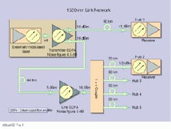
Figure 1 shows a 1550-nm network consisting of an externally modulated distributed feedback (dfb) laser with a typical output of +6 dBm, which is input to an edfa with dual 16-dBm outputs. One of the outputs feeds a hub site located 60 km from the headend, and the other output is fed to an edfa 44 km from the headend. This edfa feeds four hubs located 30 km from the line edfa.
The main contributions to the overall system cnr at the hub sites are due to the individual noise contributions from the laser, edfas, and receiver. These individual noise contributions will be examined in detail below, and the overall cnr for Hubs 1 and 2 derived as an example.
Laser carrier-to-noise ratio
Laser noise, known as relative intensity noise (rin), contributes to the overall system cnr of 1550-nm links. rin is the broadband noise due to spontaneous emission that results in incoherent light. Semiconductor lasers produce coherent light by stimulated emission. Spontaneous emission causes the laser`s output intensity and frequency to fluctuate about a median value. This output fluctuation is called the laser`s rin, while the fluctuation in frequency is called the laser`s "spectral linewidth."
Typical rin values for dfb lasers with modulation frequencies less than 1 GHz are -160 to -165 dB/Hz. Noise is also added by thermal noise and the circuitry driving the electro-optical modulator. The cnr due to the laser rin is given below as:
Laser cnr = m2/2(rin)(BW) (1)
where
BW = channel bandwidth = 4 MHz for ntsc systems
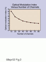
m = single channel modulation index. Typical values for electronically third-order predistorted commercial external modulated systems are shown in Fig. 2.
From Equation 1, laser cnr in decibels can be expressed as:
Laser cnr (dB) = 20logm-10log(2BW) - rin (2)
edfa carrier-to-noise ratio
Like lasers, edfas also produce internal noise due to spontaneous emission. This is called amplified spontaneous emission (ase). Due to the nonlinear nature of the photodiode, after detection the ase is converted to:
sp-sp noise current: spontaneous-spontaneous beat noise
s-sp noise current: signal spontaneous beat noise.
The s-sp beat noise is the most significant of the above three. The edfa cnr due to s-sp is given by:
edfa cnr = (snrin)(m2)/2(BW)F (3)
where snrin = input signal-to-noise ratio and is given by:
snrin = lPin /2hc
where
Pin =optical input power
F=edfa noise factor
NF =edfa noise figure = 10 logF
l =laser wavelength in meters
h =Planck`s constant = 6.63-34 Js
c =speed of light = (3)(108 ms-1)
edfa cnr = l (m2)Pin/hc(4BW)F (4)
From Equation 4, edfa cnr in decibels can be expressed as:
edfa cnr (dB) = 158.92 + 20logm -10log(4BW)+Pin (dBm) - NF (5)
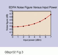
Equation 5 shows that the edfa cnr increases with increased input power and lower noise figure. The noise figure of the edfa is also a function of the input power, so for accurate cnr calculations, the manufacturer`s data for noise figure at a particular edfa input should be used. edfas have a typical noise figure of 4.5 dB for a +6 dBm input. The noise figure increases as the optical input is increased as shown in Fig. 3.
Optoelectronic receiver cnr
Optical receivers convert the AM modulated optical input power into a current output via a detector. The most common detector used is a semiconductor pin diode. The sensitivity of a diode detector is measured by the quantum efficiency h, and responsivity r.
The quantum efficiency is given by:
h = number of hole - electron pairs generated/number of incident photons
Typical pin diodes operating at 1300 and 1550 nm have h of greater than 80%.
The responsivity is given by:
r = Iout /Rxin
where
Iout = current out of the detector
Rxin= incident optical power
r = hql/hc 6)
where
q = electronic charge = (1.602)(10-19)
From Equation 6, the responsivity, r, for a quantum efficiency, h, of 80% is calculated as 1.0 A/W at 1550 nm.
Photodetectors generate two types of noise, shot noise, which is random in nature, and thermal (or Johnson) noise, which is due to the load resistor and amplifier used to amplify the detected signal.
Shot noise cnr
Shot noise limits the cnr that can be achieved for a given optical power. cnr due to shot noise is given by:
cnrshot = m2r Rxin/4qBW (7)
In decibels, this can be expressed as:
cnrshot (dB) = 151.93 + 20logm - 10log(BW) + 10logr + Rxin(dBm) (8)
Amplifier noise cnr
Thermal noise, including amplifier noise, is usually specified in terms of a "thermal noise equivalent current"
The cnr due to amplifier (thermal) noise is given by:
cnramp=(mrRxin)2/2
where (mrPin)2 /2 is the mean-square, per-channel signal current, and BW is the bandwidth in hertz.
In decibels this can be simplified to:
cnramp (dB) = 161.94 + 20log(mr) +2Rxin(dBm)-10log(2BW) (10)
The overall receiver cnr is then a sum of the cnr contribution of shot noise and amplifier noise. This is simply the addition of cnr values in Equations 8 and 9 on a 10log basis.
Interferometric intensity noise
Interferometric intensity noise (inn) also causes degradation in the cnr. inn is caused by double back-scattered light interfering with nonscattered light, resulting in low-frequency noise in the forward direction. Typically, a 0.5-dB degradation in cnr is observed for fiber spans up to 60 km long.
Overall system cnr
Using the equations given above, the designer can determine his final cnr at a hub or node site by first evaluating the individual cnrs due to the laser, transmitter edfa, any line (repeater) edfa, and finally the receiver. The overall cnr is then simply given by the addition of these cnrs on a 10log basis. As an example, the end-of-line cnrs for Hubs 1 and 2 shown in Fig. 1 will be derived below.
Given these parameters for Hub 1:
Number of channels = 80 ntsc
BW = 4 MHz
m = 0.029 for 80 channels (from Fig. 2)
laser rin = -160 dB/Hz
Transmitter edfa input, Pin = 6 dBm
Transmitter edfa noise figure = 4.5 dB
Receiver input, Rxin = 1.0 dBm
Receiver responsivity, r = 1.0 A/W at 1550 nm
the cnr calculation is accomplished as follows:
Laser cnr from Equation 2 = 60.2 dB
Transmitter edfa cnr from Equation 5 = 57.6 dB
Receiver cnrshot from Equation 8 = 56.2 dB
Receiver cnramp from Equation 10 = 64.2 dB
The overall system cnr at Hub 1 is given by:
cnrHub1 = -10log(10-6.02 + 10-5.76 +10-5.62 + 10-6.42)
cnrHub1 = 52.6 dB
Due to inn, a 0.5-dB cnr degradation will be observed in this link. So the cnr at Hub 1 would be specified as 52.1 dB.
cnrHub1 = 52.1 dB
Meanwhile, Hub 2 is fed via a line edfa with a 5-dBm optical input and a noise figure of 5 dB. edfas in the field usually have an input isolator to prevent backreflections. The addition of this passive loss results in a higher noise figure. The cnr contribution from this amplifier has to be added to that of the laser, transmitter edfa, and receiver (optical input 1.5 dBm), as shown below:
Laser cnr from Equation 2 = 60.2 dB
Transmitter edfa cnr from Equation 5 = 57.6 dB
Line edfa cnr from Equation 5 = 56.1 dB
Receiver cnrshot from Equation 8 = 56.7 dB
Receiver cnramp from Equation 10 = 65.1 dB
Adding on a 10log basis gives:
cnrHub2 = -10log(10-6.02 + 10-5.76 + 10-5.61 + 10-5.67 + 10-6.51)
cnrHub2 = 51.2.
Allowing for inn, this link, which is longer than Hub 1, should be specified for a cnr of 50.5 dB.
cnrHub2 = 50.5 dB
This paper presents simplified equations to enable the network designer to quickly determine overall cnr in broadband 1550-nm systems employing one or more edfas. Designers must also pay attention to sbs effects, which can cause severe degradation in cnr. sbs is a nonlinear fiber effect which restricts the amount of power that can be launched into fiber. Most commercial externally modulated transmitters have sbs suppression built in, enabling up to 16 dBm of launch power.
cnr is only one of the parameters used in defining the performance of networks. When designing networks, the designer must also bear in mind distortions such as composite triple beat and composite second order. u
References
1. J.P. Powers, An Introduction to Fiber Optic Systems, Aksen Associates Inc. Publishers, Boston, MA, 1993.
2. R.C. Cotten, "Lightwave Transmission Applications," Cable Television Laboratories Inc., Boulder, CO, 1993.
Harj Ghuman is business development manager of ATx Telecom Systems Inc., a wholly owned subsidiary of Scientific-Atlanta Inc., Naperville, IL.Fig. 3. Noise figures of erbium-doped fiber amplifiers increase as the optical input power increases.
Get answers -- fast!
To get the quickest response to your question, contact the appropriate person listed below.
Bulletin Board, reprints
Kathleen McIntosh
Tel: (603) 891-9203
E-mail: [email protected]
Subscriptions
Ruth King
Tel: (918) 832-9349
E-mail: [email protected]
New products, calendar
Marcy Koff
Tel: (603) 891-9238
E-mail: [email protected]
Media kit, editorial calendar
Gladys Haberman
Tel: (603) 891-9239
E-mail: [email protected]
News and features
Stephen M. Hardy
Tel: (603) 891-9454
E-mail: [email protected]


