
Passive optical networks (PONs) are critical to future broadband access networks. The current COVID-19 pandemic and work from home (WFH) practices have highlighted the necessity for reliable, high-speed internet access around the world as communities struggle to adapt to a more virtual environment. Higher downstream and upstream bandwidth driven by cloud computing, online gaming, file sharing, and video conferencing applications is forcing the network to evolve towards more symmetrical traffic transport.
Service providers witnessing the increasing bandwidth surge and ever-changing consumer traffic patterns are being confronted by an inevitable bandwidth exhaust on their fiber networks built on legacy GPON technology. In response, they are turning to 10-Gbps symmetric variants of PON (XG(S)-PON, 10G-EPON, and NG-PON2) for both brownfield and greenfield deployments to address converged residential, enterprise, and 5G any-haul applications. In other words, while many subscribers are not necessarily going to upgrade to 10G services immediately, the limited aggregate bandwidth in a 2.5G GPON is driving the transition to 10G-PON.
PON standards
Gigabit Passive Optical Networks (GPON), defined by the ITU-T G.984 series, was ratified more than 15 years ago and over time G.984.5 emerged to support the coexistence of different NG-PON technologies. GPON continues to operate at 1490 nm downstream and 1310 nm upstream while XG(S)-PON, per the ITU-T G.9807.1 recommendation, uses a 1577-nm downstream and a 1270-nm upstream wavelength. Since there is no wavelength overlap, XG(S)-PON service can be deployed as an overlay on the same optical plant as the GPON service. Similarly, NG-PON2 technology which bundles multiple wavelengths in the upstream and downstream according to the ITU-T G.989 standard, is also spectrally compatible.
Optical distribution network
The PON optical distribution network (ODN) – which comprises the optical fiber, cable ducts, poles, along with the civil and fiber construction aspects – is a significant expense and a major portion of the total PON deployment cost. For NG-PON services to be commercially viable, service providers are eager to re-use and leverage the existing optical infrastructure while maintaining compatibility with legacy services.
While optical splitters do not have different wavelength-dependent losses, there are valid concerns relating to the actual outside plant cable segments and how well they might transport NG-PON wavelengths. In FTTx networks, there are typically three distinct cable segments, each of which can impair NG-PON wavelengths (see Figure 1):
- Feeder cable - segment from optical line terminal (OLT) to fiber distribution terminal (FDT)
- Main cable being routed through a densely populated area.
- Newer cables are fiber-rich, employing from 72 to 1,728 cores.
- Distribution cable - segment from (FDT) to fiber distribution point (FDP), also known as fiber access terminal (FAT)
- Intermediate cable or link between feeder cable and subscriber drop cable
- The FDP is used to distribute optical cables for a second time.
- Drop/subscriber cable - segment from FDP to rosette/access termination box (ATB)
- Generally used outdoors - aerial, direct buried, or ducted installations.
- Fiber counts can vary from 1-12 cores.

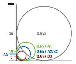
- Category A - Fibers for access networks
- G.657.A1 (10-mm minimum design radius)
- G.657.A2 (7.5-mm minimum design radius)
- Category B - Fibers for short distances at the end of access networks
- G.657.B2 (7.5-mm minimum design radius)
- G.657.B3 (5-mm minimum design radius).
Considering G.657 category A fiber is fully compliant with G.652 single-mode fiber, it can be deployed throughout the general feeder and distribution network. Category B is not fully compliant with G.652; however, it is capable of low macrobending losses at very small bend radii and is intended for applications inside buildings or near buildings. The fourth and most recent ITU-T G.657 revision from 2016 modifies the usage of category A fibers to include all applications (feeder, distribution, and subscriber).
In FTTx applications, fiber distribution panels, termination boxes, splice enclosures, and wall-mount outlets have limited space and thus require tighter fiber angles. So fibers with smaller bend radii are desirable for installers. Due to its greater resistance to bending losses (macrobends), particularly at longer wavelengths, G.657.A2 fiber is preferred because it is also simpler and easier to install. On the other hand, service providers are cramming more fibers into smaller tubes, leading to a situation where there is less room for fibers to move before touching a buffer tube wall, thereby creating possible microbends.
Even though G.657.A2 is compatible and used in conjunction with G.652.D fiber, there are subtle geometry differences between the two fiber types that FTTx technicians should be aware of. Depending on the vendor or when the fiber was developed, the improved macrobend performance of G.657.A2 fiber was sometimes achieved by adjusting the mode field diameter (MFD). Differences in MFD not only cause slightly higher splice losses when splicing these two different fiber types together, but bending loss is typically correlated, i.e., as the MFD increases, so does the bending loss and vice versa.
Cable technology advances in recent years have enabled both low-loss performance and improved macrobend performance while maintaining the 9.2-µm MFD diameter of legacy G.652.D fibers. This enables seamless integration into pre-existing GPON systems. However, ODNs that pre-date 2013 should be carefully examined because they probably do not employ bend-insensitive cables that conform to these requirements.
Fiber bending in NG-PON systems
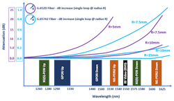
The importance of fiber bending performance for NG-PON services operating at longer wavelengths cannot be ignored. As we’ve discussed, there are two types of bending in fiber networks – macrobending and microbending. While both types produce loss as a function of wavelength and fiber type, the mechanisms and how they manifest differ (Figure 3).

Going where no fiber has gone before
Fiber in an NG-PON is going places where legacy GPON fiber applications have not existed or gone before. Fiber is now commonplace inside businesses, shopping centers, and is more frequently being employed in mobile fronthaul applications to feed cellular and Wi-Fi sites on top of light poles, building rooftops, and other non-traditional fiber infrastructure.
As fiber encounters a new diverse habitat and set of environmental elements, there are many points along the route where microbending and macrobending can occur. Bend-related faults in the feeder, distribution, or subscriber segment can be due to the cabling process, but generally they are a result of poor installation practices or improper fiber management. In some cases, bending in optical splitters in the outside plant (OSP) can be overlooked as a potential failure point. Despite stringent testing in accordance with ITU-T and Telcordia recommendations, optical component vendors can miss small microcracks during production or the final testing stage, and these minute imperfections can degenerate into a more serious fracture over time when the splitter is exposed to thermal stress in more “hostile” environments. In addition, the vast majority of optical splitters used in GPON systems today have only been verified in production using legacy GPON wavelengths that are less susceptible to bending. Thus, any bending issues related to longer wavelength operation might have gone untested or undetected.
Putting theory into practice
An optical time domain reflectometer (OTDR) is the instrument of choice to identify and locate bend-related losses in PON architectures. The vast majority of GPON systems in use today were tested at 1310/1490 nm or 1310/1550 nm wavelengths during the fiber construction phase (Figure 4). But very few ODNs now considered for NG-PON co-existence have been verified at the longer downstream wavelengths – unfortunately, legacy test practices will not have discovered bend-related losses for NG-PON service.
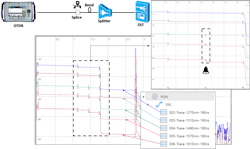
Using a CWDM OTDR to simulate the various 10G-PON systems being deployed today, let us take a closer look at potential bend-related losses as a function of wavelength on a simple FTTx architecture using G.652D fiber only (Figure 5). In the test example below, the following test wavelengths were used to approximate and simulate:
- GPON – 1310 nm upstream, 1490 nm downstream
- XG(S)-PON – 1270 nm upstream, 1570 nm downstream (actual is 1577 nm)
- NG-PON2 (TWDM PON) – 1610 nm downstream (actual is ~1596 to ~1603 nm).
Test summary
- Fusion splice - detected and located at 1.134 km by all five test wavelengths and the loss was consistent and accurately measured.
- Optical splitter - loss verified at all five test wavelengths and found to be consistent, indicating no bending or microcracks in construction
- Macrobending – detected at 1.447 km by longer 1490-nm, 1570-nm, and 1610-nm wavelengths, but missed by both 1270-nm and 1310-nm shorter wavelengths. Depending on the severity of the macrobend and fiber type, the loss could be significant at the longer wavelengths
- XGS-PON Upstream Loss @ 1270 nm = < 0.01 dB (below OTDR splice loss threshold)
- GPON Upstream Loss @ 1310 nm = < 0.01 dB (below OTDR splice loss threshold)
- GPON Downstream Loss @ 1490 nm = 0.253 dB
- XGS-PON Downstream Loss @ 1570 nm = 0.921 dB
- NG-PON2 TWDM Downstream Loss @ 1610 nm = 1.115 dB
- Note: Considering the zero loss at the shorter wavelengths and varying losses at the longer wavelengths, the event at 1.447 km can be confidently identified as a bend.
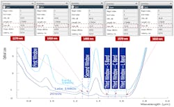
- Total Link Loss (Including spectral attenuation of fiber, splitters, bending and splices but excluding any co-existence filter losses; Figure 6)
- XGS-PON Upstream Loss @ 1270 nm = 18.36 dB
- GPON Upstream Loss @ 1310 nm = 12.93 dB
- GPON Downstream Loss @ 1490 nm = 13.37 dB
- XGS-PON Downstream Loss @ 1570 nm = 13.33 dB
- NG-PON2 TWDM Downstream Loss @ 1610 nm = 13.56 dB
- Note: XG(S)-PON uses a TDMA burst to transmit upstream signals - good OSNR is required to ensure reliable transmission and reception.
Takeaways and conclusions
- Optical link budgets – Vary by ODN class and PON type. However, 29 dB is often used as a “loose” loss budget for both XGS-PON and NG-PON2 for Class N1/N2 applications. This reasonably healthy link budget can be adversely affected by bending losses at NG-PON downstream lambdas.
- Spectral losses – XGS-PON (1270 nm) upstream signal will have much higher loss due to fiber attenuation compared to other PON services, especially older fibers that are not optimized for full-spectrum operation.
- Existing GPON splitters – Need to have wide operating wavelength range (1260 nm to 1650 nm0 splitters (U-Grade) to not affect NG-PON wavelengths and cause additional insertion loss.
- Co-existence elements – Additional loss needs to be considered in the overall link budget.
- As a rule of thumb, factor ± 0.8-dB loss for GPON, ± 1.4-dB for XGS-PON, and ± 1.1-dB loss for NG-PON2 TWDM (excludes WM1 mux).
- Test equipment
- Optical light source (OLS) and optical power meter (OPM) – Good for verifying insertion loss at the PON operating wavelengths. A specialized NG-PON OLS can be connected at the co-existence (CEx) filter, and an OPM calibrated at the specific PON wavelengths is used to verify the total insertion loss.
- OTDR – Ideal for detecting and locating bends in a xPON fiber. Historically, 1310-nm and 1550-nm wavelengths have been used to detect bending in GPON and other applications. However, 1625-nm or 1650-nm wavelengths are often used to check “worst case” scenario for NG-PON2 (TWDM and P-to-P) downstream signals operating in the L-band; this also holds true for DWDM L-Band systems that might be used in the xPON backhaul segment. A CWDM OTDR is useful to simulate and characterize attenuation in PON systems since several wavelengths per the ITU-T G.694.2 CWDM grid are very close to the PON operating wavelengths. For new co-existence PON systems, the following ODN parameters can be re-verified using a purpose-built OTDR:
- Total insertion loss of the link
- Total optical return loss of the link
- Loss of discrete events (splice, connector)
- Reflectance of any discrete event (splice, connector)
- Potential micro and macro bends.
References
1. ITU-T Rec. G.652 series: Characteristics of a single-mode optical fibre and cable.
2. ITU-T Rec. G.657 series: Characteristics of a bending-loss insensitive single-mode optical fibre and cable.
3. ITU-T Rec. G.671 series: Transmission characteristics of optical components and subsystems.
4. ITU-T Rec. G.984 series: “Gigabit-capable passive optical networks (GPON).”
5. ITU-T Rec. G.987 series: “10-Gibabit-capable passive optical networks (XGPON).”
6. ITU-T Rec. G.9807.1 series: “10-Gigabit-capable symmetric passive optical network (XGS-PON).”
7. ITU-T Rec. G.983 series: “Broadband optical access systems based on passive optical networks.”
8. ITU-T Rec. G.989 series: 40-Gigabit-capable passive optical networks (NGPON2).
9. TIA FOTP-8, Measurement of Splice or Connector Loss and Reflectance Using an OTDR.
10." One fibre everywhere?” by Vanessa Diaz, Corning Optical Fiber, Fibre-Systems, Issue 4, 2014.
11. OFS Optics, How to Speak “Fiber Geek,” Article 2, 2017 – “Critical Optical Parameters – Attenuation.”
12. TR-423 PON PMD Layer Conformance Test Plan, Broadband Forum, Issue 1, January 2019.
13. IEC 60793-1-47:2017 Measurement methods and test procedures – Macrobending loss.
Mike Venter is vice president, fiber product development, at VeEX Inc. He has been with VeEX since its inception in 2006 and is currently responsible for the company’s fiber-optic product and business development worldwide. He has held several RF, microwave, and optical product engineering and management roles in the telecom market for over 35 years and fiber test and measurement since 1989.
About the Author
Mike Venter
Vice President, Fiber Product Development
Mike Venter is vice president, fiber product development, at VeEX Inc. He has been with VeEX since its inception in 2006 and is currently responsible for the company’s fiber-optic product and business development worldwide. He has held several RF, microwave, and optical product engineering and management roles in the telecom market for over 35 years and fiber test and measurement since 1989.
Voices of the Industry

