Innovations in optical transmission systems continue to emerge in response to ever-increasing data traffic demand. Coherent transmission equipment has maintained its bit-rate trajectory to increase capacity per fiber and decrease cost per bit. On the optical fiber side, the industry has responded with innovative terrestrial fibers that provide a further increase in capacity per fiber and increase the distance over which a given fiber capacity can be achieved. This article reviews how a combination of advanced optical fiber and advanced coherent transmission can enable superior transmission performance.
Optical fiber innovations
The latest generation of terrestrial optical fibers available today has the lowest attenuation values ever seen in commercial products, which reflects a collective recognition within the optical fiber vendor community that ultra-low attenuation remains an essential fiber attribute. Some of the recently introduced long-haul terrestrial fibers also have large effective area (Aeff). The basic notion here is that the light is spread over a wider cross-sectional area, thus reducing the peak optical power in the center of the core and reducing the impact of nonlinear signal distortion (Figure 1). Ultimately, this translates into longer reach, higher transmission capacity, or higher system margin, all of which are important considerations when long-haul networks are designed.
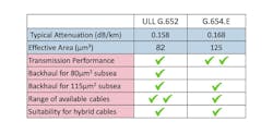
The emergence of G.654.E fibers, however, does not mean the end of the G.652 fiber era. First, G.652 fibers may in some instances offer even lower attenuation than G.654.E fibers. Second, due to differences in macrobend performance characteristics, G.652 fibers may be available in a wider range of cable designs and fiber coating form factors (both 200 and 250 µm) compared to G.654.E fibers. Finally, if used as a terrestrial backhaul for space-division multiplexed (SDM) subsea routes or branches consisting of 80-µm2 fibers, G.652 fiber in the terrestrial portion will deliver better mode field diameter matching to the subsea fiber and reduce the splice loss at the terrestrial/subsea interface.
The general consensus is that submarine SDM systems that are being designed today favor regular or moderately large Aeff, typically 80 – 115 µm2 (Figure 2). If submarine fiber has Aeff of 80 µm2, ultra-low-loss G.652 terrestrial fiber (also 80 µm2) provides the best possible mode field diameter matching and may, therefore, be a better fit for the terrestrial section. In the scenario in which the submarine fiber has the Aeff of ~115 µm2, three fiber Aeff options for the terrestrial section should be considered: 80 µm2, 115 µm2, and 125 µm2. Since 80-µm2 and 125-µm2 effective areas are somewhat equidistant from 115 µm2, both options have equal technical merit in terms of splicing to a subsea fiber section.
Finally, it is worth noting that both fiber types can be used in a hybrid cable, whereby some portion of the cable consists of conventional G.652.D fiber and the rest is reserved for an advanced fiber (i.e., ultra-low-loss G.652 or G.654.E). In such a cable, conventional G.652.D fiber can be used to provide connectivity for metro networks (where ultra-low attenuation specifications are not always needed), while advanced fiber can be reserved for more demanding long-haul routes. Use of hybrid cable is a common practice today around the world.
Coherent transponder innovations
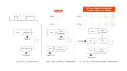
Figure 3 shows a basic comparison between three types of transponder. The first, in Figure 3a, is an amplitude modulation with direct detection (IM-DD) design – sometimes called on/off keying (OOK) modulation. IM-DD uses a simple “Morse code” style of modulation at the transmitter and a very simple photodetector in the receiver. The combination of the type of modulation and the lack of signal processing is why the performance is limited to 10 Gbps per wavelength, with a reach of around 2,500 km (see the sidebar “Capacity-Reach Product” at the end of this article).
Use of 40-Gbps coherent was very short-lived before being replaced by 100-Gbps coherent, enabled by faster electronics (from 12 Gbaud to 32 Gbaud). Higher wavelength data rates drive down the cost and power consumption per Gbps and drive up productivity in terms of bringing new capacity into service. For operators that sell services, higher fiber capacity means higher service revenues over fixed-cost fiber assets. For operators with an internal need for capacity, such as hyperscale content providers, fiber capacity is the ultimate fuel for their respective business models.
Beyond first-generation coherent
The next step, shown in Figure 3c, was to add signal processing to the transmitter as well as the receiver. This enabled a range of features, including higher-order modulation such as PM-16QAM. Data rates for coherent transmission have grown from 200 Gbps to 400 Gbps, 600 Gbps and, most recently, 800 Gbps.
The longer the reach at a given data rate, the wider the market opportunity for this technology, with data center Interconnect (DCI) from 10 to 200 km; metro up to 600 km; long-haul up to 2,500 km; and ultra-long-haul >2,500 km. But what could be achieved using fifth-generation coherent transmission over new G.654 large Aeff fiber?
Fifth-generation coherent
A critical demonstration was planned for the OFC show in March 2020, but COVID-19 prevented this demonstration from being held at the conference. Instead, the partnership of Corning and Infinera went ahead with lab demonstrations of Infinera’s ICE6 transponder over Corning TXF G.654.E optical fiber. When the initial 800 km at 800 Gbps delivered ample transmission margin, an additional 200 km of TXF fiber was added to the test bed, extending it to 1,000 km at 800 Gbps over long amplifier spans, still with very comfortable transmission margins. Further field trials over real network links of G.652 and G.655 fiber resulted in 800 Gbps transmission over <1,000 km.
Summary
The incredible partnership of high-quality, advanced optical fiber with evolving coherent transponder performance is essential to deliver the capacity we need to feed ever-growing bandwidth demand. The capability these technologies already deliver today will satisfy that demand in the foreseeable future, and engineers are already devising techniques to extend this capacity even further.
Geoff Bennett is director, solutions and technology, at Infinera.
Sergejs Mokovejs is market and technology development manager at Corning.
SIDEBAR: Capacity-Reach Product
Capacity and reach are antagonistic variables – as data rates increase, or reach is extended, impairments in optical fiber tend to “push back.” Coherent digital signal processing can compensate for linear impairments such as chromatic dispersion and polarization-mode dispersion. Limited nonlinear compensation is also possible today, but operating in a fiber with a larger effective area and/or high chromatic dispersion (such as G.654.E fiber) can help to mitigate nonlinear penalties.
The most indicative metric is the product of capacity and reach at a given wavelength data rate.
Amplification vs. Regeneration
Optical amplification, using technologies such as erbium-doped fiber amplifiers (EDFAs) or Raman amplifiers, is relatively inexpensive, but each amplifier adds a tiny amount of noise to the signal. At some point the accumulated noise has to be “cancelled out” by digital regeneration, which is much more expensive.
Therefore, when the term “optical reach” is used, this actually refers to the reach before regeneration is needed.


